Ultra-wideband V-UHF antenna

a wideband, antenna technology, applied in the direction of antennas, antenna feed intermediates, electrical devices, etc., can solve the problems of incompatibility of space requirements with vehicle dimensions, inability to meet the radio range required for ground-ground links, and inability to use land-based moving objects. achieve the effect of efficiency and gain

Inactive Publication Date: 2005-11-17
THALES SA
View PDF10 Cites 11 Cited by
  • Summary
  • Abstract
  • Description
  • Claims
  • Application Information

AI Technical Summary

Benefits of technology

[0016] It provides for a single wideband antenna giving discontinuity-free coverage of more than one decade, especially fro

Problems solved by technology

However, these antennas have drawbacks which make them unsuited for use in a land-based moving object.
Indeed, their efficiency is either too low for the radio range required for ground-ground links, as in the case of air-borne antennas, or their space requirement is incompatible with the dimensions of the vehicl

Method used


Image

  • Ultra-wideband V-UHF antenna
  • Ultra-wideband V-UHF antenna
  • Ultra-wideband V-UHF antenna

Examples


Embodiment Construction

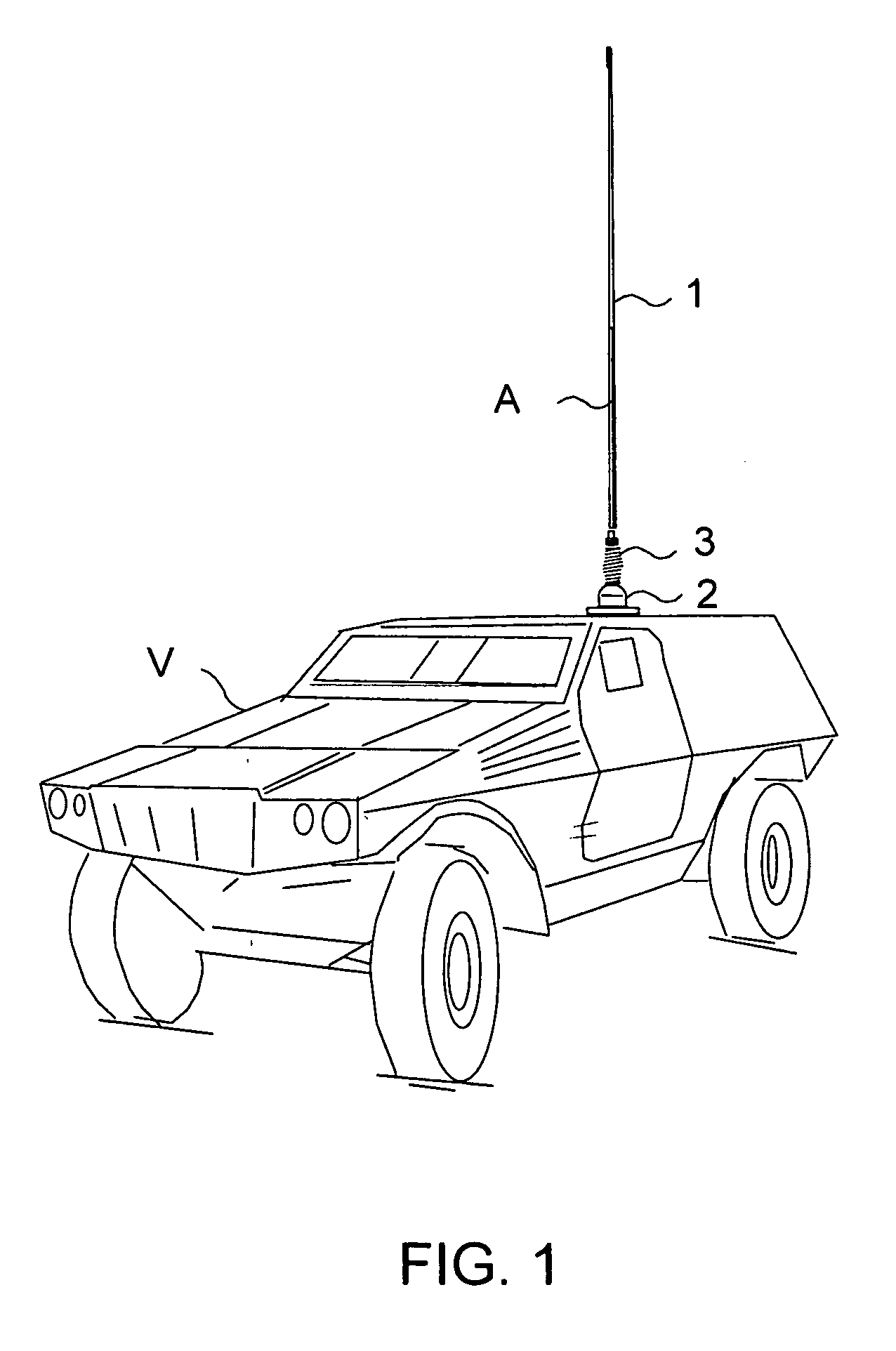
[0022]FIG. 1 exemplifies an antenna A installed in the vehicle V. This antenna is constituted for example by a radiating element 1 which takes the form of a whip and a base 2 used to fix the antenna to the carrier vehicle and usually comprising a power supply network to enable the maximum transfer of power from the transmitter / receiver to the radiating unit 1. In order to protect the antenna from accidental impact with obstacles, a flexible element 3 is interposed at its base. This flexible element, which is known to those skilled in the art, shall not be described in detail for the sake of simplification.

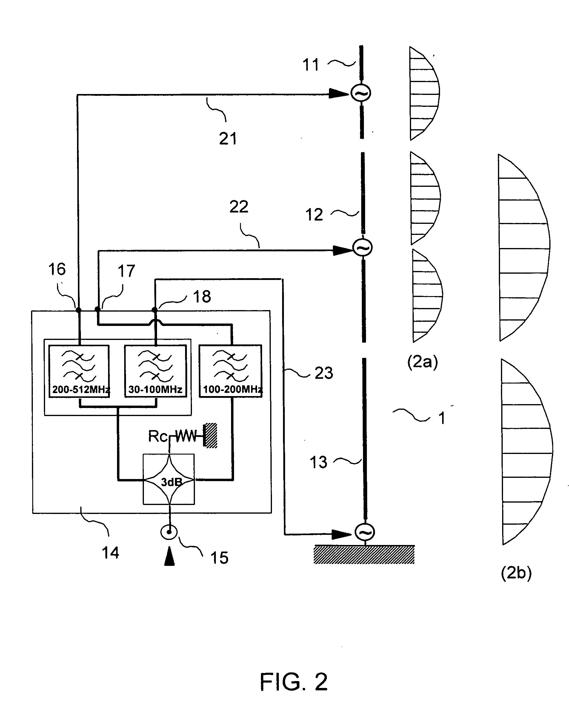
[0023]FIG. 2 shows a block diagram and the principle of operation of an antenna according to the invention, working in the 30 to 512 MHz band. The values of this band are given by way of illustration and in no way restrict the scope of the invention.

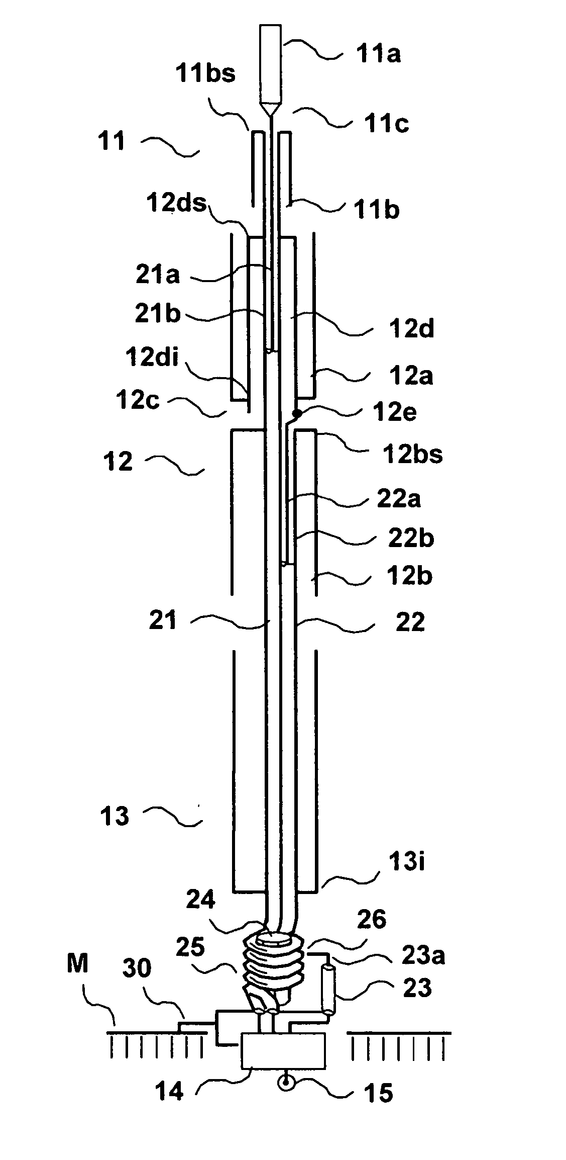
[0024] The antenna A comprises for example: [0025] a radiating assembly 1 constituted by two collinear dipoles 11 and 12 and one mon...


PUM


Abstract

A wideband antenna system is capable of radiating or receiving radio-frequency signals in a given frequency band, comprising at least two substantially collinear radiating elements, wherein each element radiates in one frequency band, a first radiating element working in the [Fhinf, Fhsup] frequency band, a second radiating element working in the [Fminf, Fmsup] frequency band. At the hinge frequencies, these two elements participate in the radiation.

Description

BACKGROUND OF THE INVENTION [0001] 1. Field of the Invention [0002] The invention relates to an ultra-wideband antenna systems working both in sending or transmission mode and in reception mode without re-matching. It is designed for example for the frequencies band varying from 30 to 512 MHz, from the VHF (Very High Frequencies) up to the UHF (Ultra High Frequencies) [0003] This band encompasses especially the classic bands: the usual VHF-FM or VHF frequency modulation band ranging from 30 to 88 MHz, the VHF-AM or VHF amplitude modulation band ranging from 100 to 160 MHz and the UHF-AM (UHF-amplitude modulation) band ranging from 225 to 400 MHz. [0004] 2. Description of the Prior Art [0005] Modern transmission-reception (T / R) stations are capable of working in all the frequency bands varying from 30 to 512 MHz. However, the existing antenna systems that are associated with them, especially those designed to be installed in mobile telephones, provide optimum operation only in the ac...

Claims


Application Information

Patent Timeline
IPC IPC(8): H01Q5/00H01Q5/10H01Q5/40H01Q21/10H01Q21/30
CPCH01Q5/00H01Q9/22H01Q5/40H01Q21/30H01Q21/10
Inventor BUI HUNG, FREDERIC NGO
Owner THALES SA
Why Eureka
Try Eureka