
Plane ultra-wide band antenna

An ultra-wideband antenna, plane technology, applied in antennas, antenna arrays, resonant antennas, etc., can solve the problems of inability to meet the requirements of conformal characteristics, inability to obtain full-space radiation characteristics, and limit the miniaturization of antennas, so as to meet the needs of small ultra-wideband antennas. With communication system, the effect of simplifying the feeding structure

Inactive Publication Date: 2007-03-14
UNIV OF SCI & TECH OF CHINA
View PDF0 Cites 11 Cited by
  • Summary
  • Abstract
  • Description
  • Claims
  • Application Information

AI Technical Summary

Problems solved by technology

[0003] The International Institute of Electrical and Electronics Engineers "Antennas and Propagation" magazine (IEEE Transaction on Antennas and Propagation, No. 2, 1998, pages 294-295) once introduced the elliptical monopole antenna as a typical structure for obtaining a large impedance bandwidth, but due to this type In actual application, the antenna needs a large ground plane perpendicular to the radiation sheet, so that on the one hand, this type of antenna only has energy radiation in the upper half space containing the radiation unit, and cannot obtain the radiation characteristics in the whole space. On the one hand, due to the fact that the three-dimensional structure limits the miniaturization of the antenna and cannot meet the requirements of conformal characteristics, it is difficult to be widely used in actual communication systems, especially small systems.
[0004] In order to solve the above problems, at the 2003 IEEE Antennas Propagation Society International Symposium, Schantz proposed a bottom-fed planar elliptical UWB antenna (Bottom fed planar elliptical UWB antennas), which has a planar structure feature and can realize edge feeding to reduce the influence of the feeding structure on the pattern, but its balun structure design is complex, and the working bandwidth cannot completely cover the 3.1GHz-10.6GHz frequency range required for ultra-wideband wireless communication, so in There are still deficiencies in the application

Method used


Image

  • Plane ultra-wide band antenna
  • Plane ultra-wide band antenna
  • Plane ultra-wide band antenna

Examples


Embodiment 1

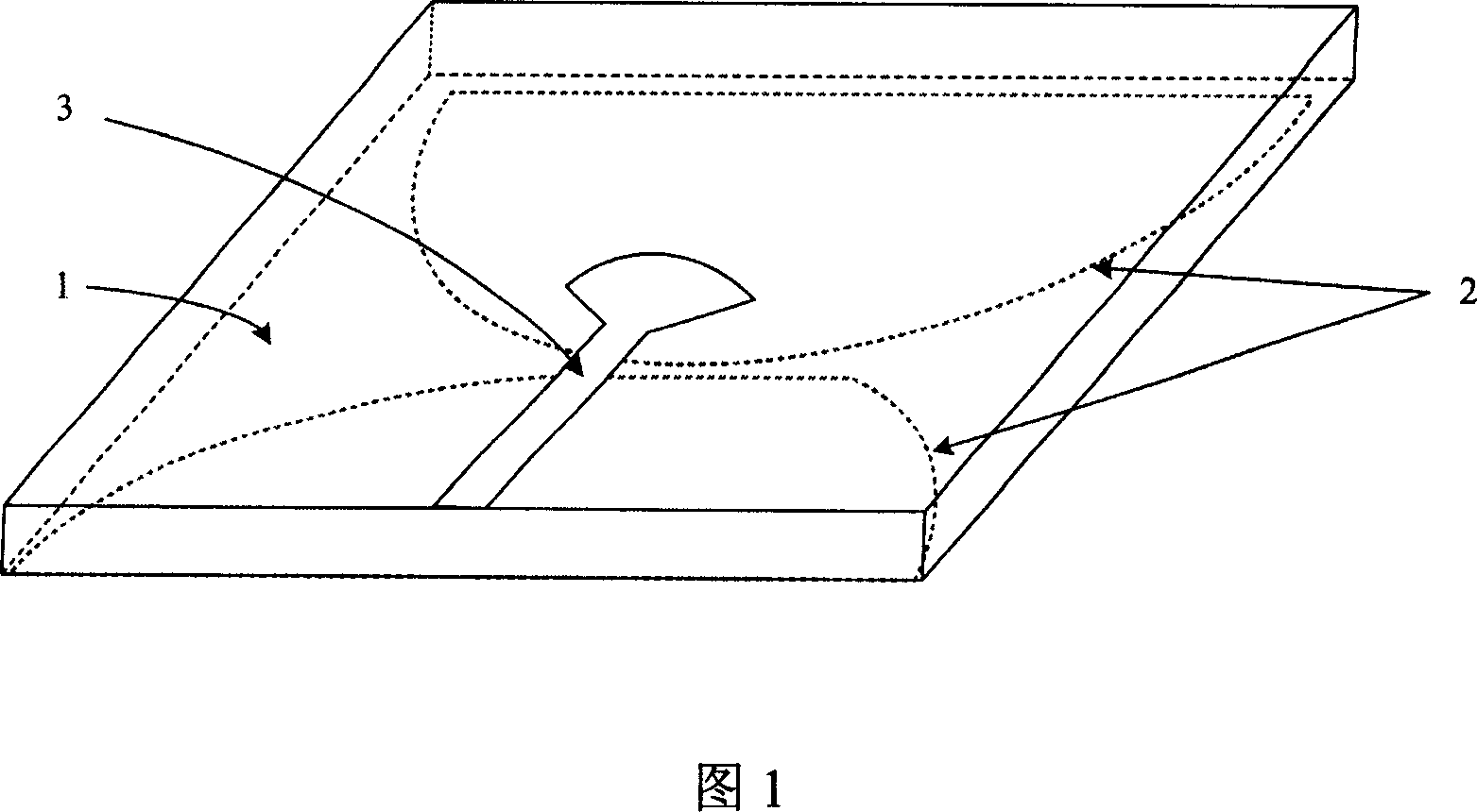
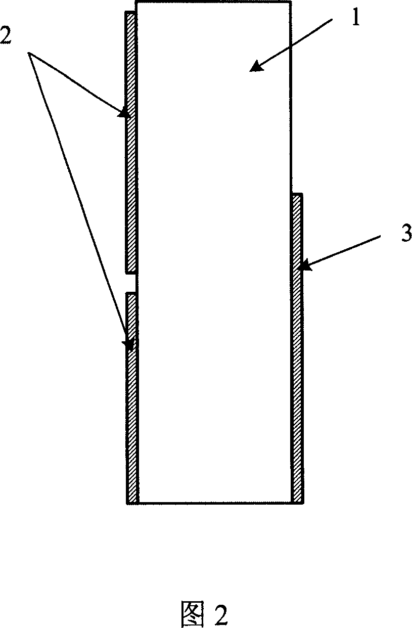
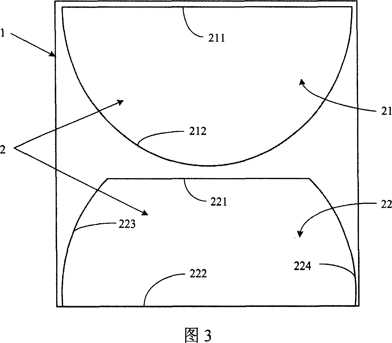
[0018] The planar ultra-broadband antenna of this embodiment can refer to the structural schematic diagram that Fig. 1 provides and the side view that Fig. 2 provides, the rear view that Fig. 3 provides and the top view that Fig. 4 provides: it is made of dielectric substrate 1, and is printed on respectively The radiation copper layer 2 and the feed copper layer 3 on both sides of the dielectric substrate are composed of three parts.

[0019] The dielectric substrate 1 has a certain dielectric constant and thickness, and its functions are: firstly, to transmit energy in the feeding transmission line, and secondly, to support the radiation copper layer and the feeding copper layer. In order to reduce the influence of the dielectric plate on the field distribution at the coupling structure, a dielectric substrate with a lower dielectric constant is usually used, and a thinner thickness is selected under the condition of ensuring a certain hardness. In this implementation exampl...


PUM


Abstract

This invention relates to plane super wide antenna, which comprises irradiation copper layer and feedback copper layer covered on positive and back planes of medium baseboard, which is characterized by the following: irradiation copper layer is composed of upper and down rows with upper unit composed of upper line edge and down ellipse edge and with down unit composed of left and right ellipse edges to form one ellipse edge and line edge; the feedback copper layer rectangle transmission band is relative to other side with upper edge relative to the center of irradiation units; the transmission band top end is in shape of fan with open angle symmetric.

Description

Technical field: [0001] The invention belongs to the technical field of ultra-wideband antennas, in particular to planar omnidirectional radiation antennas. Background technique: [0002] As a key component for radiating and receiving energy in an Ultra-Wide Band (UWB) wireless communication system, the antenna has performance requirements including a large impedance bandwidth, small size and easy conformability, and low processing cost. [0003] The International Institute of Electrical and Electronics Engineers "Antennas and Propagation" magazine (IEEE Transaction on Antennas and Propagation, No. 2, 1998, pages 294-295) once introduced the elliptical monopole antenna as a typical structure for obtaining a large impedance bandwidth, but due to this type In actual application, the antenna needs a large ground plane perpendicular to the radiation sheet, so that on the one hand, this type of antenna only has energy radiation in the upper half space containing the radiation uni...

Claims


Application Information

Patent Timeline
IPC IPC(8): H01Q1/38H01Q5/00H01Q9/16H01Q21/00H01Q5/25
Inventor 张金平徐云生王卫东
Owner UNIV OF SCI & TECH OF CHINA
Learn More