
Piezoelectric inkjet printhead and method of manufacturing the same

Inactive Publication Date: 2006-08-17
SAMSUNG ELECTRO MECHANICS CO LTD
View PDF3 Cites 17 Cited by
  • Summary
  • Abstract
  • Description
  • Claims
  • Application Information

AI Technical Summary

Benefits of technology

[0019] It is therefore yet another feature of an embodiment of the present invention to provide a method of manufacturing a piezoelectric inkjet printhead that involves a reduced number of steps and provides for enhanced alignment of the substrates constituting the printhead.

Problems solved by technology

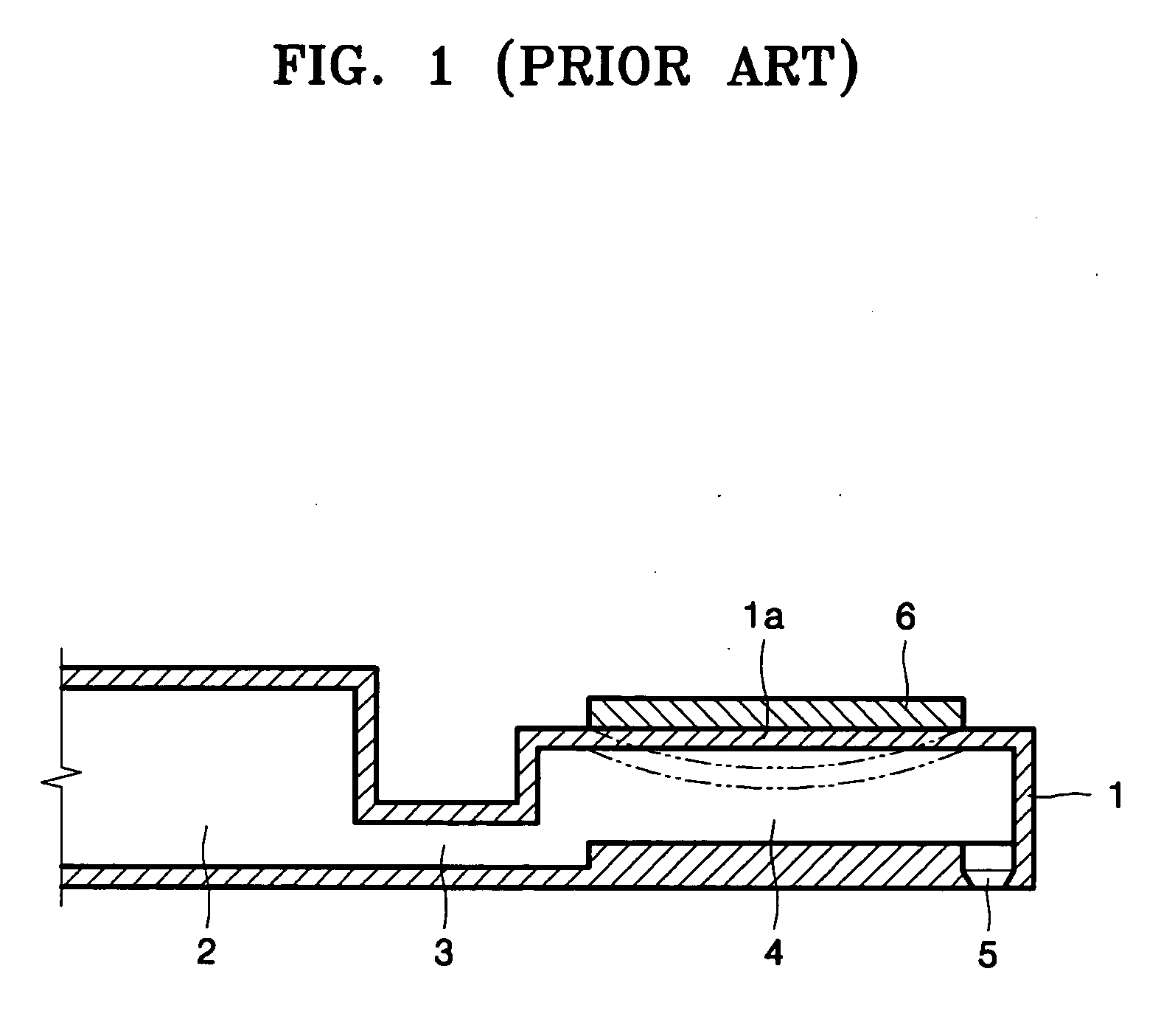
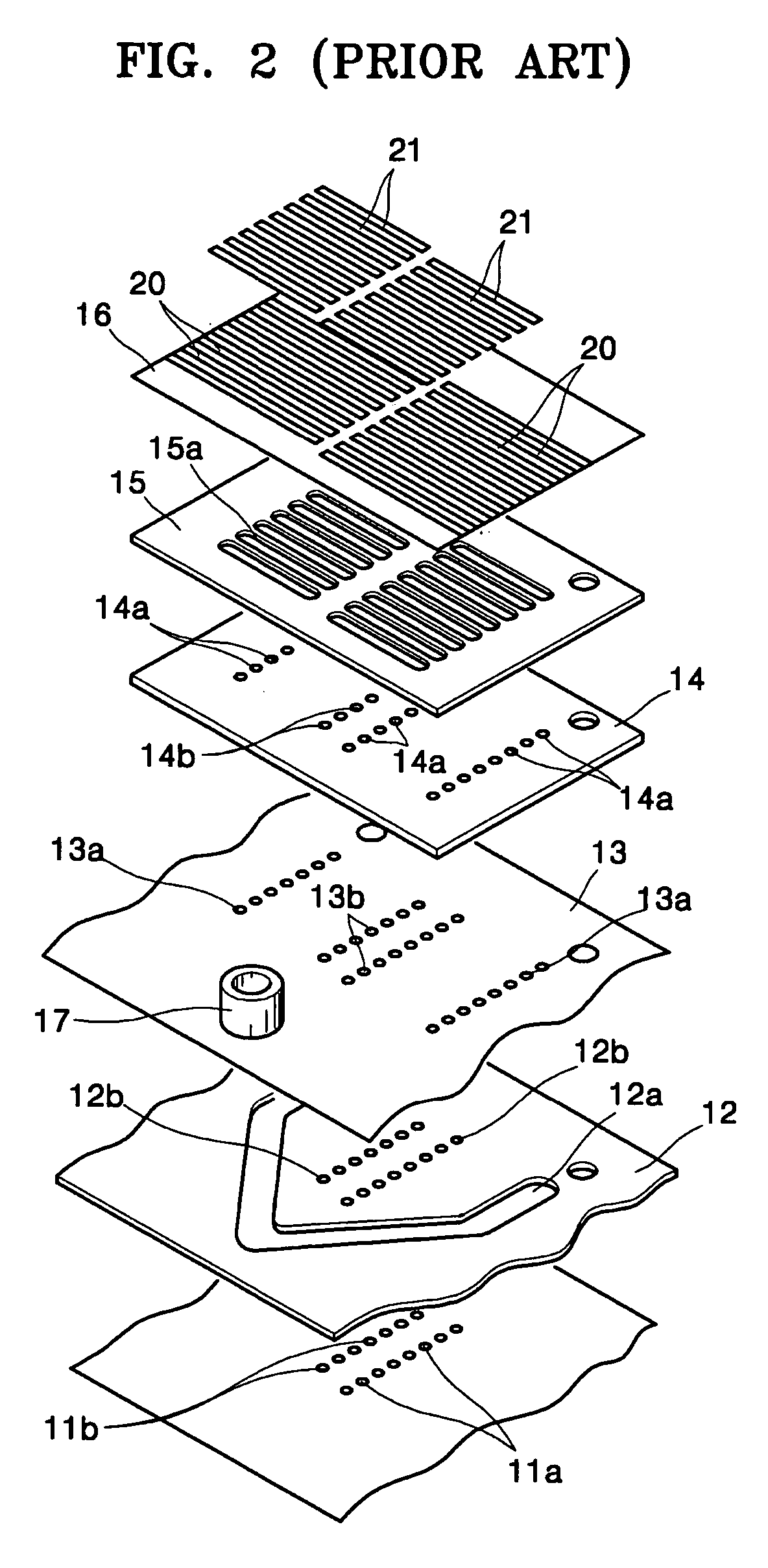
Moreover, the number of plates constituting the printhead of FIG. 2 is relatively large, so the number of processes required for aligning the plates increases, which increases the likelihood of generating an alignment error.
When an alignment error is generated, ink does not flow quickly through the ink channels, which reduces the ink ejecting performance of the printhead.
In particular, when high density printheads are manufactured in an effort to improve printing resolution, the alignment process requires significant accuracy, which leads to high manufacturing costs.
Since the plurality of plates constituting the printhead are manufactured by different methods using different materials, the manufacturing processes are complicated and bonding between materials of different kinds may be difficult, which reduces product yield.
Also, even when the plurality of plates are accurately aligned and bonded during the manufacturing process, an alignment error or deformation may be generated due to a difference in thermal expansion coefficients between materials of different kinds when the temperature the materials change.
However, the manufacturing cost of the printhead of FIG. 3 is still high, and the performance thereof at high driving frequencies for rapid printing may not be satisfactory.

Method used


Image

  • Piezoelectric inkjet printhead and method of manufacturing the same
  • Piezoelectric inkjet printhead and method of manufacturing the same
  • Piezoelectric inkjet printhead and method of manufacturing the same

Examples


Embodiment Construction

[0044] Korean Patent Application No. 10-2005-0004454, filed on Jan. 18, 2005, in the Korean Intellectual Property Office, and entitled: “Piezoelectric Inkjet Printhead and Method of Manufacturing the Same,” is incorporated by reference herein in its entirety.

[0045] The present invention will now be described more fully hereinafter with reference to the accompanying drawings, in which exemplary embodiments of the invention are shown. The invention may, however, be embodied in different forms and should not be construed as limited to the embodiments set forth herein. Rather, these embodiments are provided so that this disclosure will be thorough and complete, and will fully convey the scope of the invention to those skilled in the art. In the figures, the dimensions of layers and regions are exaggerated for clarity of illustration. It will also be understood that when a layer is referred to as being “on” another layer or substrate, it can be directly on the other layer or substrate, ...


PUM


Abstract

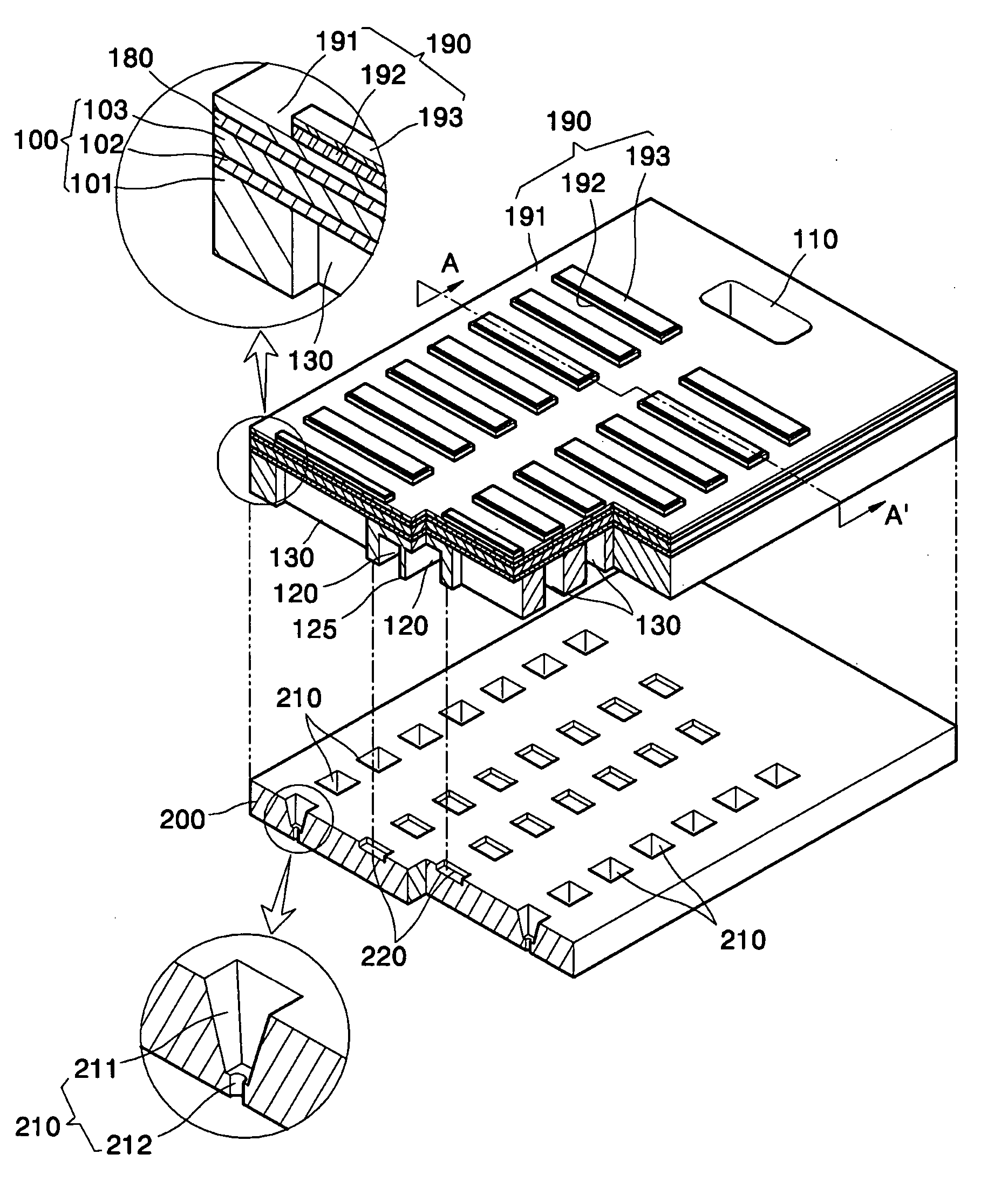
A piezoelectric inkjet printhead including an upper substrate, having an ink inlet, a manifold connected with the ink inlet, and a plurality of pressure chambers arranged along at least one side of the manifold, wherein the ink inlet passes through the upper substrate, and the manifold and the pressure chambers are formed in a lower surface of the upper substrate, a lower substrate disposed directly adjacent the upper substrate, the lower substrate having a plurality of restrictors each connecting the manifold with one end of each of the pressure chambers, and a plurality of nozzles each being formed in a position of the lower substrate that corresponds to the other end of each of the pressure chambers to vertically pass through the lower substrate, wherein the plurality of restrictors are formed in an upper surface of the lower substrate, and a plurality of piezoelectric actuators.

Description

BACKGROUND OF THE INVENTION [0001] 1. Field of the Invention [0002] The present invention relates to an inkjet printhead. More particularly, the present invention relates to a piezoelectric inkjet printhead manufactured from two silicon substrates, and a method of manufacturing the same. [0003] 2. Description of the Related Art [0004] An inkjet printhead is a device that ejects fine ink droplets onto a desired position of a print medium in order to print an image of a predetermined color. Inkjet printheads may be roughly classified into two types according to the ink ejection method used. The first type is a thermally-driven inkjet printhead that generates bubbles in ink using a heat source and ejects ink using an expansion force of the bubble. The second type is a piezoelectric inkjet printhead that deforms a piezoelectric element and ejects ink using pressure applied to the ink by deformation of the piezoelectric element. [0005]FIG. 1 illustrates a sectional view of a piezoelectri...

Claims


Application Information

Patent Timeline
IPC IPC(8): B41J2/045
CPCB41J2/14233B41J2/161B41J2/1623B41J2/1628B41J2/1629B41J2/1631B41J2/1632B41J2/1637B41J2002/14306B41J2002/14411B41J2002/14419B41J2/045
Inventor LEE, JAE-CHANGCHUNG, JAE-WOOKANG, SUNG-GYU
Owner SAMSUNG ELECTRO MECHANICS CO LTD
Learn More