Quantization device, quantization method, and recording medium

Active Publication Date: 2019-12-05
NEC CORP
View PDF0 Cites 0 Cited by
  • Summary
  • Abstract
  • Description
  • Claims
  • Application Information

AI Technical Summary

Benefits of technology

[0029]According to the present invention, the number of steps related to optimization of

Problems solved by technology

In the rate calculation, it is necessary to array the respective coefficient values in series, and to process these in accordance with syntax, and accordingly, it is difficult to perform the parallel processing.
Meanwhile, in the optimization of the last coefficient position in the last coefficient position determination unit 230, it is difficult to calculate the pieces of RD cost of the respective last coefficient position candidates in parallel even when the approximation is used, and the parallel processing thereof is difficult.
Meanwhile, even when the technology described i

Method used


Image

  • Quantization device, quantization method, and recording medium
  • Quantization device, quantization method, and recording medium
  • Quantization device, quantization method, and recording medium

Examples


first example embodiment

[Explanation of Configuration]

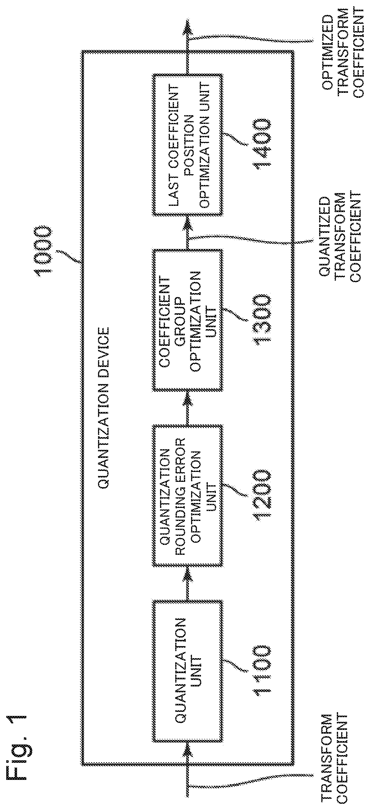
[0109]FIG. 8 is a block diagram illustrating a configuration example of a quantization device 1000A according to a first example embodiment of the present invention. The quantization device 1000A is a device that performs quantization processing of quantizing an image.

[0110]The illustrated quantization device 1000A has a similar configuration to that of the quantization device 1000 illustrated in FIG. 1 except that a last coefficient position optimization unit 1500 is used in place of the last coefficient position optimization unit 1400.

[0111]FIG. 9 is a block diagram illustrating a configuration example of the last coefficient position optimization unit 1500 illustrated in FIG. 8. As will be described later, the last coefficient position optimization unit 1500 operates as a processing unit that acquires candidates for an output data length that minimizes cost to which a degradation of image quality due to compression and a compression ratio are taken i...

second example embodiment

[Explanation of Configuration]

[0142]FIG. 13 is a block diagram illustrating a configuration example of a quantization device 1000B according to a second example embodiment of the present invention.

[0143]The illustrated quantization device 1000B has a similar configuration to that of the quantization device 1000 illustrated in FIG. 1 except that a last coefficient position optimization unit 1600 is used in place of the last coefficient position optimization unit 1400.

[0144]FIG. 14 is a block diagram illustrating a configuration example of the last coefficient position optimization unit 1600 illustrated in FIG. 13.

[0145]As illustrated in FIG. 14, the last coefficient position optimization unit 1600 of this second example embodiment is composed of: a rate calculation unit 1610; a coefficient cost calculation unit 1620; a last coefficient cost calculation unit 1630; and a last coefficient cost determination unit 1640.

[0146]The last coefficient position optimization unit 1600 of this sec...

examples

[0174]Next, an operation of a mode for embodying the present invention will be described by using a specific example.

[0175]An information processing device illustrated in FIG. 17 includes: a control device 10; a parallel processing device 20; a storage medium 30 for storing image data; and a program memory 40.

[0176]The parallel processing device 20 is composed of a plurality of processing units (PUs) 21. In the illustrated example, the parallel processing device 20 is composed of sixteen pieces of the processing units 21. However, it is a matter of course that the number of processing units 21 is not limited to this.

[0177]In the information processing device illustrated in FIG. 17, programs for achieving the functions of the respective blocks illustrated in FIG. 8 and FIG. 13 are stored in the program memory 40. Then, in accordance with the program instructed to be executed by the control device 10 and stored in the program memory 40, the parallel processing device 20 executes the p...


PUM


Abstract

This quantization device includes a processing unit which calculates the cost involved in a plurality of data lengths in consideration of the compression ratio and image quality deterioration due to compression of an image. A process for calculating the cost is partially common among the plurality of data lengths. The processing unit distributes the common process for the plurality of data lengths, executes the distributed processes in parallel, and thereby determines, as an optimal data length, one data length the cost for which is the lowest, among the plurality of data lengths.

Description

TECHNICAL FIELD[0001]The present invention relates to a quantization device, a quantization method, and a recording medium.BACKGROUND ART[0002]H.264 / AVC (Advanced Video Codec) is widely used as a standard for compressing a video. Moreover, H.265 / HEVC (High Efficiency Video Codec) is known as a next-generation video compression standard oriented toward compression of a high-resolution video such as 4K / 8K pictures.[0003]Such a video compression technology is composed of prediction processing, transformation / quantization processing, and entropy encoding. In the prediction processing, processing of reducing redundancy between frames or in a frame is performed. In the transformation / quantization processing, there is performed processing of reducing spatial redundancy by transforming a space component of a prediction residual signal into a frequency component and quantizing the frequency component. In the entropy encoding, there is performed processing of dynamically allocating variable-l...

Claims


Application Information

Patent Timeline
IPC IPC(8): H04N19/124H04N19/436H04N19/46H04N19/176
CPCH04N19/436H04N19/176H04N19/46H04N19/124H04N19/126H04N19/147H04N19/18
Inventor IGARASHI, HIROAKI
Owner NEC CORP
Why Eureka
Try Eureka