Planar light source and image display

Inactive Publication Date: 2006-08-17
ORMON CORPORATION
View PDF4 Cites 15 Cited by
  • Summary
  • Abstract
  • Description
  • Claims
  • Application Information

AI Technical Summary

Benefits of technology

[0007] It is an object of the present invention to provide a plane source of light of the type of emitting light from both surfaces featuring a good light utilization efficiency. The invention further provides a plane source of light of the type of emitting li

Problems solved by technology

In this liquid crystal display device, the two liquid crystal display portions comprising the liquid crystal display panel and the back light are arranged back to back resulting in an increase in the thickness of the liquid crystal display device arousing a problem in that equipment must have a large space for incorporating the liquid crystal display device.
When the display i

Method used


Image

  • Planar light source and image display
  • Planar light source and image display
  • Planar light source and image display

Examples


Example

First Embodiment

[0062]FIG. 5 is a disassembled perspective view illustrating the constitution of a plane source of light 41 according to a first embodiment of the present invention, and FIG. 6 is a side view thereof. The plane source of light 41 is constituted by a point source of light 42, a light guide plate 43 and a prism sheet 44, the point source of light 42 being buried in a corner portion of the light guide plate 43 and the prism sheet 44 facing the back surface of the light guide plate 43.

[0063] The light guide plate 43 is formed like a nearly rectangular flat plate by using a transparent resin or a glass having a high refractive index, such as a polycarbonate resin, an acrylic resin or methacrylic resin. FIG. 7 is a back view of the light guide plate 43. On the back surface of the light guide plate 43, a planar light-emitting region 45 of a rectangular shape that substantially becomes a plane source of light is surrounded by a non-emitting region 46, and a hole 47 for fit...

Example

Second Embodiment

[0094]FIG. 30 is a plan view illustrating a plane source of light 72 according to a second embodiment of the invention, and FIG. 31 is a disassembled perspective view thereof. In the plane source of light 72 according to this embodiment, a plurality of point sources of light 42 are arranged facing the central portion of the short side of the light guide plate 43. On the planar light-emitting region 45 on the back surface of the light guide plate 43, there are formed many deflecting patterns 59 in an arcuate shape with the light-emitting region of the point sources of light 42 nearly as a center. The deflecting patterns 59 are formed in nearly a right-angled triangular shape in cross section as described in the first embodiment. Prism surfaces may be formed on the side surfaces of the light guide plate 43 at positions facing the point sources of light 42 so as to increase the spread of light entering into the light guide plate 43 from the point sources of light 42. ...


PUM


Abstract

A plane source of light (back light) of the type of emitting light from both surfaces featuring a good light utilization efficiency and without permitting the external light to transmit through a display device even when it is combined with display panels of the transmission type. Light is introduced from a point source of light into a light guide plate. Many deflecting patterns of a triangular shape in cross section are formed in a recessed manner in a surface (pattern surface) on the side opposite to a light-leaving surface of the light guide plate. A prism sheet forming a plurality of arcuate prisms is arranged on a position facing the pattern surface of the light guide plate. Light propagating through the light guide plate is totally reflected by the deflecting pattern and goes out from the light-leaving surface nearly perpendicularly thereto. Light propagating through the light guide plate transmits through the deflecting patterns, goes out aslant, and is bent by the prisms into a direction nearly perpendicular to the pattern surface as it transmits through the prism sheet.

Description

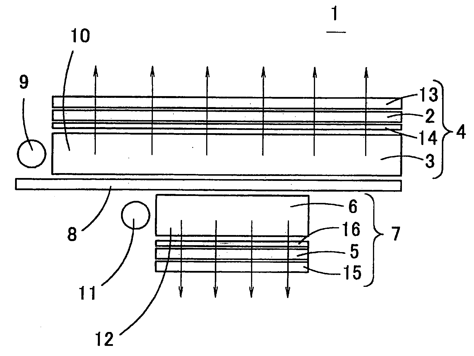
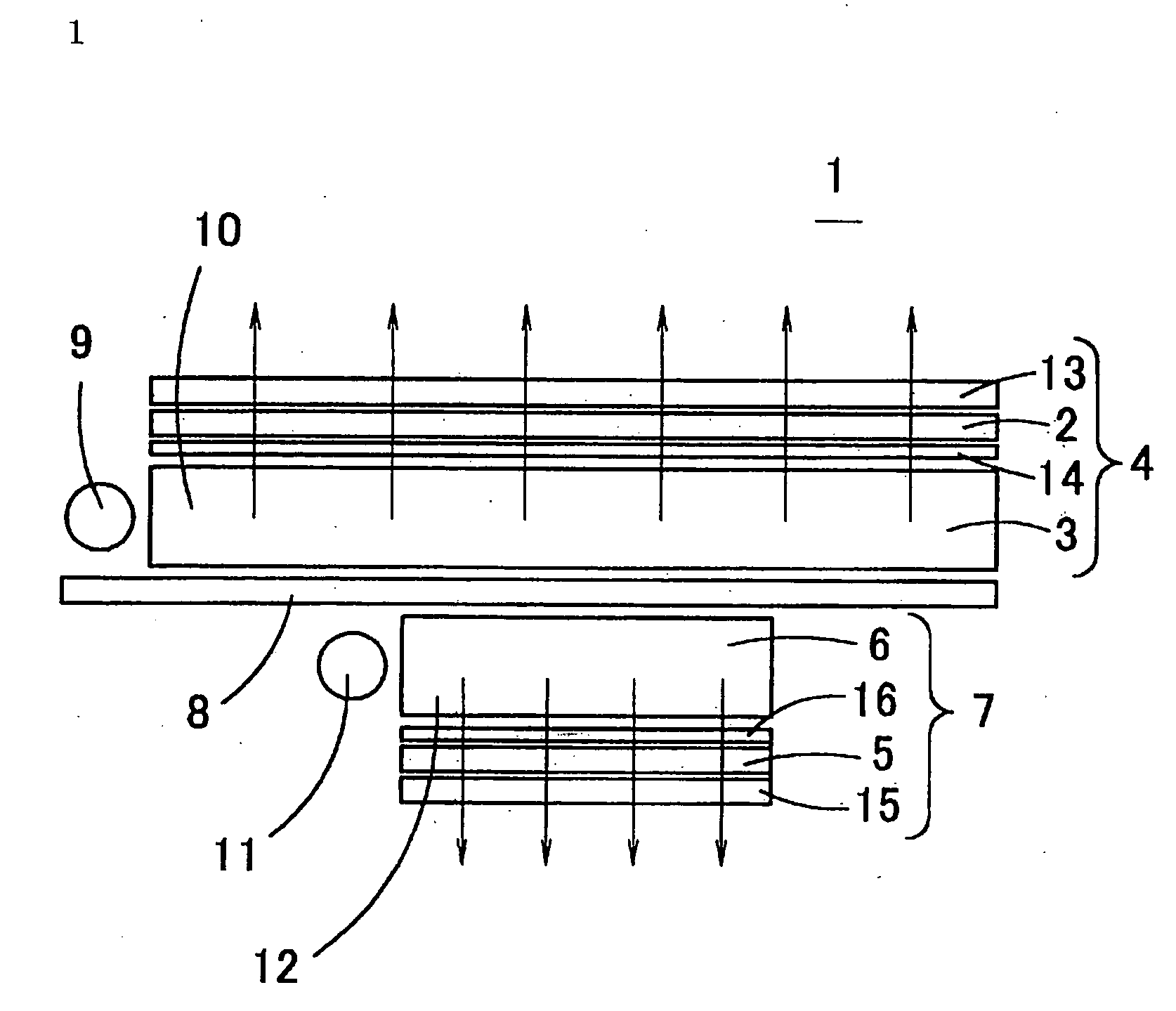
FIELD OF THE INVENTION [0001] This invention relates to a plane source of light of the type of emitting light from both surfaces and to an image display device. BACKGROUND OF THE INVENTION [0002]FIG. 1 is a view schematically illustrating the structure of a conventional liquid crystal display device of the type of double-sided display. In this liquid crystal display device 1, diffusion plates 13 and 14 are arranged on the front surface and on the back surface of a liquid crystal display panel 2, and a back light 3 comprising a source of light 9 and a light guide plate 10 is arranged on the back surface side of the liquid crystal display panel 2 through the diffusion plate 14 thereby to constitute a liquid crystal display portion 4 of the front surface side. Further, diffusion plates 15 and 16 are arranged on the front surface and on the back surface of a liquid crystal display panel 5, a back light 6 comprising a light source 11 and a liquid guide plate 12 is arranged on the back su...

Claims


Application Information

Patent Timeline
IPC IPC(8): F21V7/04F21V8/00G02B6/00G02F1/13357
CPCG02B6/0018G02B6/0036G02B6/0038G02B6/0061G02B6/0063G02F1/133615G02F2001/133342G02F1/133342G02F1/1335
Inventor UENO, YOSHIHIROSHINOHARA, MASAUKI
Owner ORMON CORPORATION
Why Eureka
Try Eureka