Blind bolt and blind nut

a technology of blind bolts and nuts, applied in the direction of fastening means, screws, dowels, etc., can solve the problems of insufficient strength in the whole structure, inability to rotate the locking piece for use, and the locking piece may be subject to breakage, so as to smoothly rotate the locking piece and separate the rotary protrusions

Inactive Publication Date: 2006-08-17
KOYOKIZAI
View PDF13 Cites 35 Cited by
  • Summary
  • Abstract
  • Description
  • Claims
  • Application Information

AI Technical Summary

Benefits of technology

[0016] Preferably, to smoothly rotate the locking piece within the oblong hole, the rotation supporting grooves of the bolt main body are formed in a longitudinal shape axially extending towards the piece holding grooves from the position of one of the rotary protrusions, with the locking piece being accommodated in the oblong hole, and the rotation supporting grooves are provided with an inclined plane so as to smoothly separate the rotary protrusions.

Problems solved by technology

The support shaft is lower in strength than the locking piece and a bolt, and the structure is prone to shear force, resulting in insufficient strength in the whole structure.
(2) Even though the support shaft slightly deforms or bends, the locking piece may not be rotated for use.
(3) If the outside diameter of the support shaft is made larger to obtain more strength, the locking piece may be subject to breakage due to stress concentration in the shaft hole therethrough.
(4) Since the bolt main body and the locking piece are made of high-strength and hard materials, more processing like cutting works for the shaft hole will require increasing production costs.
In particular, since the bolt described above requires a processing to link both ends of the spring to the locking piece and the pin main body, production costs will further grow.
Therefore, additional processing steps like cutting works, which increases production costs and will also reduce the bolt strength.
In addition, since a sliding groove is formed through almost the entire length of the bolt and a longitudinal shaft hole is provided on the side thereof, the reduction in bolt strength and increasing production costs will become more severe.

Method used


Image

  • Blind bolt and blind nut
  • Blind bolt and blind nut
  • Blind bolt and blind nut

Examples


first embodiment

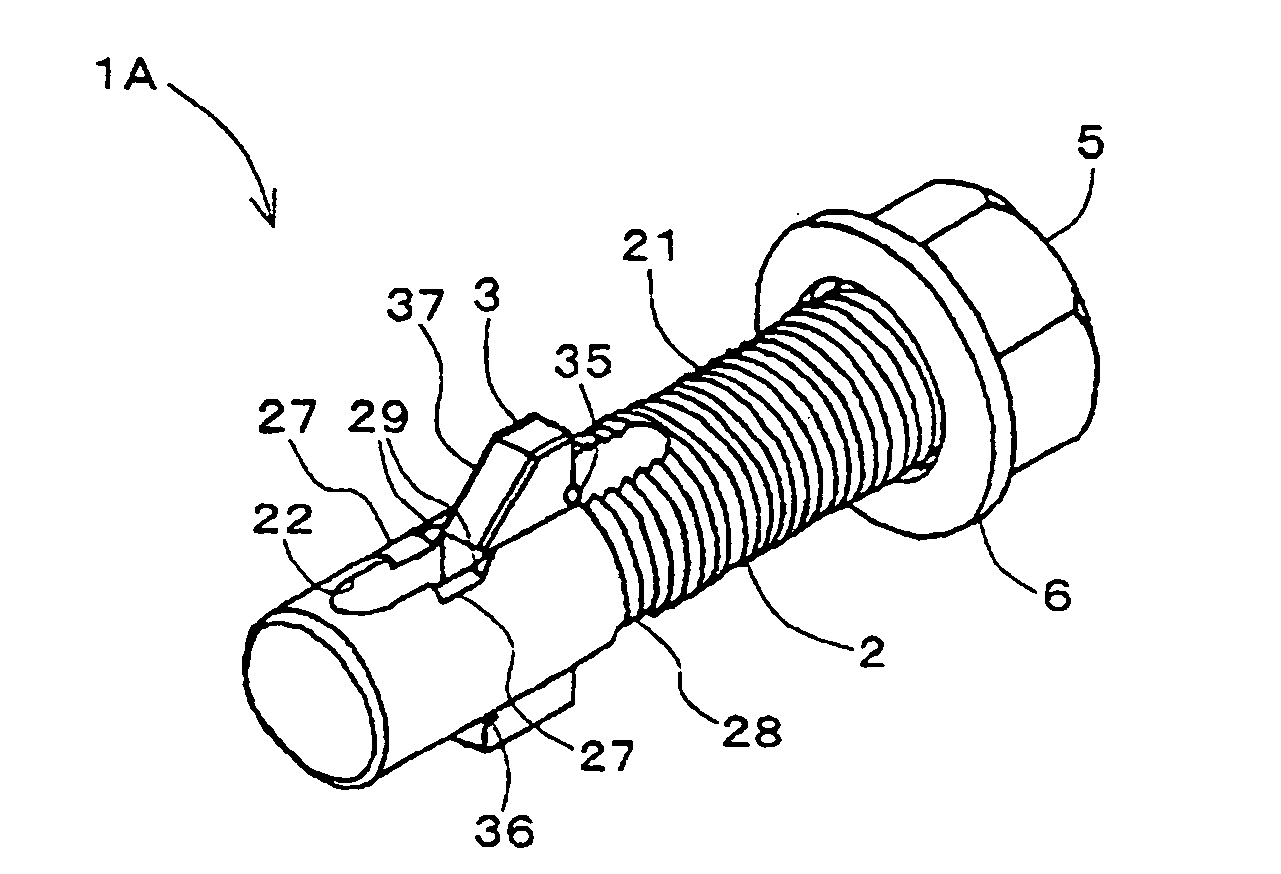
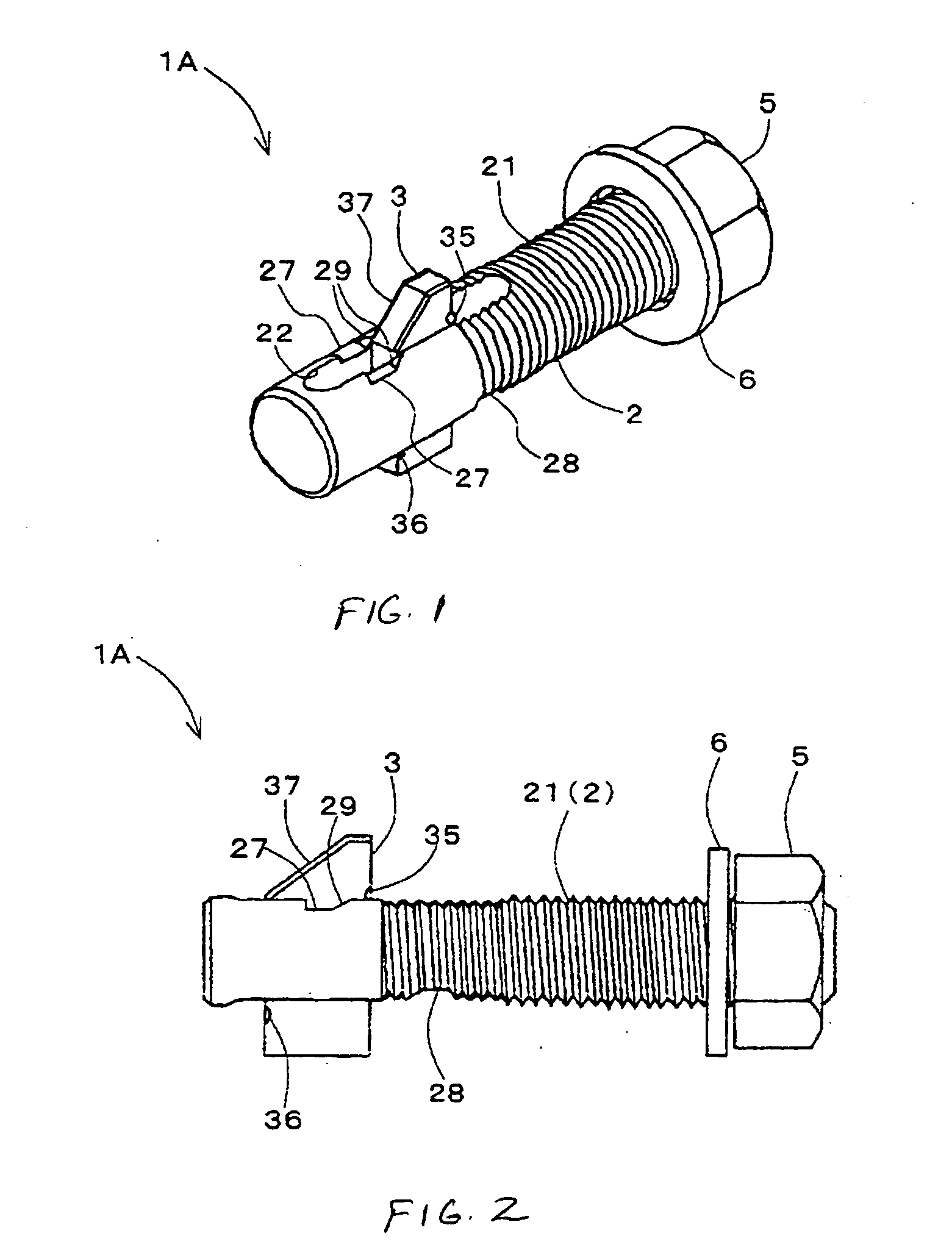
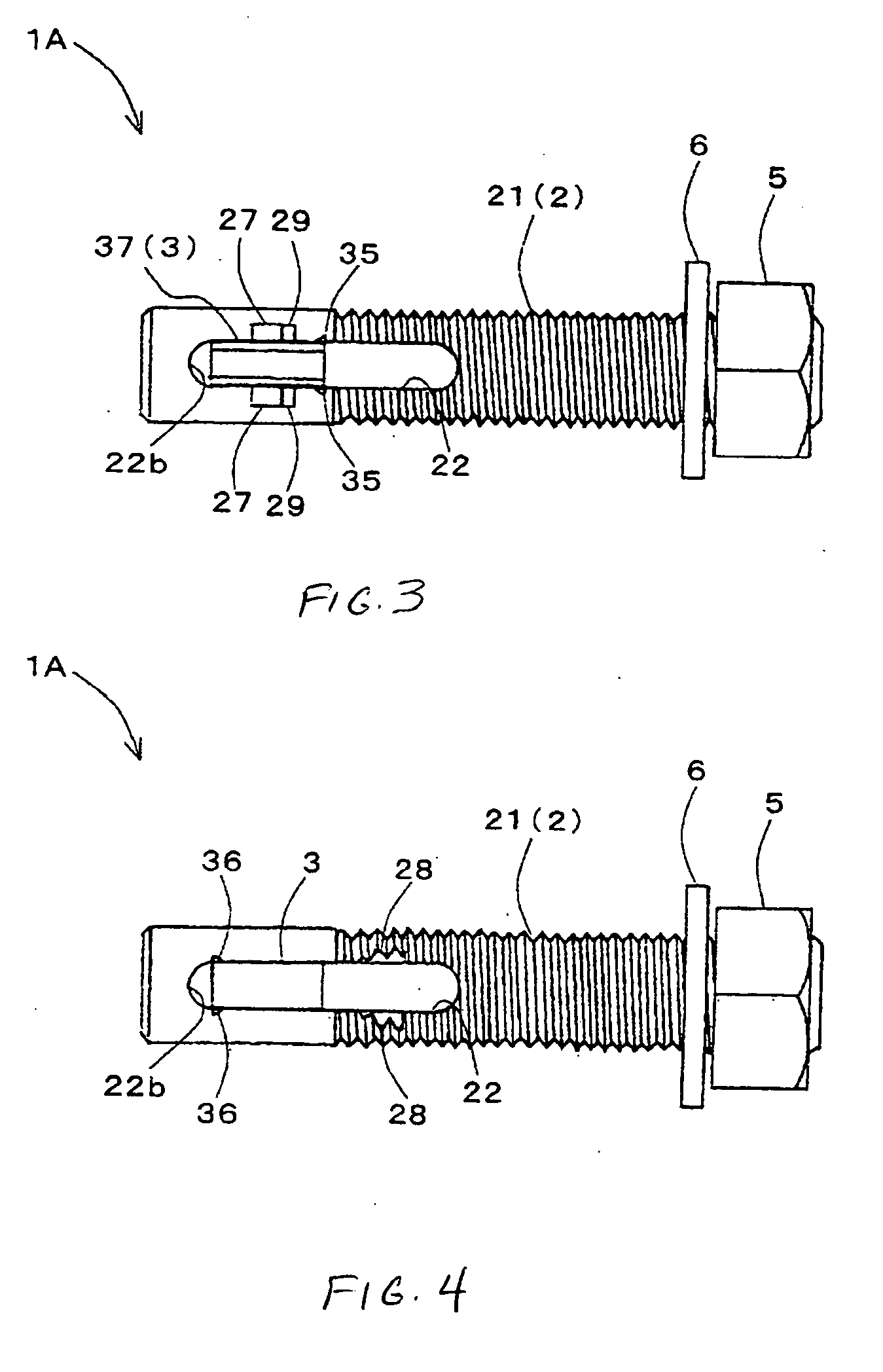
[0043] Referring to FIGS. 1 to 5, a blind bolt 1A of the first embodiment includes a bolt main body 2 having a male screw part 21 provided at one end thereof and an oblong hole 22 formed on the axis thereof at the other end, the oblong hole 22 rotatably holding a locking piece 3 to lock a beam X (FIG. 7). In addition, the male screw part 21 of the bolt main body 2 is screwed through a washer 6 into a nut 5, thereby fastening a member Y (FIG. 7) to the beam X, together with the nut 5 and said locking piece 3.

[0044] Each component shown in the first embodiment will be described in further detail. Referring to FIGS. 1 to 3, there is shown a pair of rotation supporting grooves 27, 27 provided along the oblong hole 22 of the bolt main body 2 so as to face with each other on edges of one opening of the oblong hole 22 on the axis thereof The locking piece 3 is made in the form of a nearly rectangular solid, and on edges of the long sides thereof, a pair of rotary protrusions 35, 35 is prov...

second embodiment

[0062] Next, referring to FIG. 14, a preferred application of the blind bolt 1B of the second embodiment will be described in detail.

[0063] If a member Y is secured to a beam X, the inside of which is inaccessible for mounting by means of the blind bolt 1B according to the second embodiment of the present invention, the locking piece 3 is completely accommodated within the oblong hole 22 as shown in FIG. 14(a), and the bolt main body 2 is inserted into a prepared hole h to dispose the locking piece 3 inside the beam X.

[0064] Further, as shown in FIG. 14 (b), when the bolt main body 2 is pivotally rotated approximately at an angle of 180 degrees to turn the rotation supporting grooves 27, 27 upwardly, the locking piece 3 rotates about the rotary protrusions 35, 35. Subsequently, the locking piece 3 slides the rotary protrusions 35, 35 on the rotation supporting grooves 27, 27 towards the male screw part 21. At the same time, the locking piece 3 rotates as the curved surface 38 slide...

third embodiment

[0066] Referring to FIGS. 15-21, the blind nut 11 of the present invention will be described in detail.

[0067] The blind nut 11 of the third embodiment is characterized by having no rotating shaft for a nut main body 12 and disposing protrusions within grooves for rotating the nut. In addition, if the nut main body 12 normally receives force energized by springs and other devices, it will get stuck into space between a beam X and a member Y. The third embodiment aids in overcoming this type of problem.

[0068] As shown in FIG. 15, the blind nut 11 of the third embodiment includes the nut main body 12 having a female screw hole 121 in a nearly central portion thereof and a nut frame body 13 for accommodating the nut main body 12. The nut frame body 13 is provided with a pair of arms 132, 132 extending parallel to each other and orthogonal to a flange 131 having a bolt inserting hole 131a.

[0069] Referring to FIGS. 15 to 17, the nut main body 12 is formed in the shape of nearly rectangu...


PUM


Abstract

A blind bolt and a blind nut system wherein the blind bolt comprises a bolt main body having an oblong hole and a locking piece rotatably supported within the oblong hole. The locking piece is provided with a pair of rotary protrusions and a pair of pieces holding rotary protrusions projecting outwardly. The oblong hole includes a pair of rotation supporting grooves to accommodate the rotary protrusions and support rotary motion, and a pair of piece holding grooves to accommodate the piece holding the piece holding protrusions.

Description

BACKGROUND OF THE INVENTION [0001] 1. Field of the Invention [0002] The present invention relates to a blind bolt and blind nut which are used to fasten a material to a beam or member with a rear, or back, side inaccessible for mounting. [0003] 2. Description of the Prior Art [0004] Conventionally, blind bolts and blind nuts have been used to fasten a material to a wall, or to a member inside or with a back side inaccessible for mounting. For example, a threaded pin such as that disclosed in Japanese Patent Publication No. 11-311229 rotatably supports a locking piece by a support shaft in a pin main body having a male screw part at one end thereof, and secures the end to both the locking piece and the support shaft by loosely fitting a spring into the support shaft. In addition, the spring energizes the locking piece in such a manner as being sprung out from the pin main body for use of extending even in a vertical direction. [0005] Japanese Utility Model Application No. 53-145060 d...

Claims


Application Information

Patent Timeline
Patent Type & Authority Applications(United States)
IPC IPC(8): F16B21/00F16B5/02F16B13/08F16B35/04F16B35/00
CPCF16B5/02F16B13/0808F16B35/00
Inventor ITO, KATSUO
Owner KOYOKIZAI
Why Eureka
Try Eureka