Optical tunable filter and method of manufacturing the same

a technology manufacturing methods, applied in the field of optical tunable filters, can solve problems such as the inability to attenuate ligh

Active Publication Date: 2006-08-17
SANTEC +1
View PDF9 Cites 42 Cited by
  • Summary
  • Abstract
  • Description
  • Claims
  • Application Information

AI Technical Summary

Benefits of technology

[0014] The present invention has been made in view of the above drawbacks. It is, therefore, a first object of the present invention to provide an optical tunable filter and a method of m

Problems solved by technology

Accordingly, light is prevented from being attenuated due to n

Method used


Image

  • Optical tunable filter and method of manufacturing the same
  • Optical tunable filter and method of manufacturing the same
  • Optical tunable filter and method of manufacturing the same

Examples


first embodiment

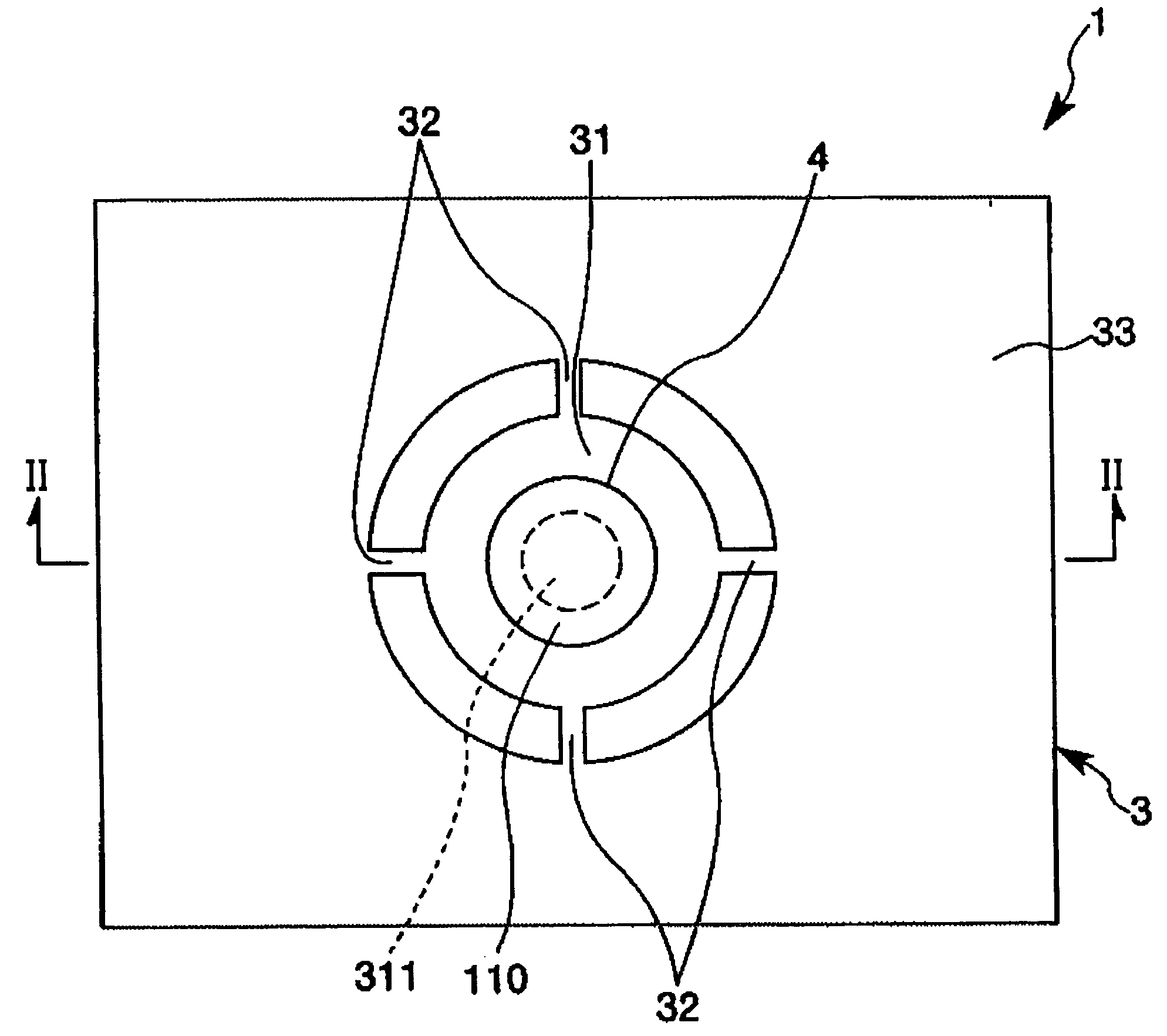
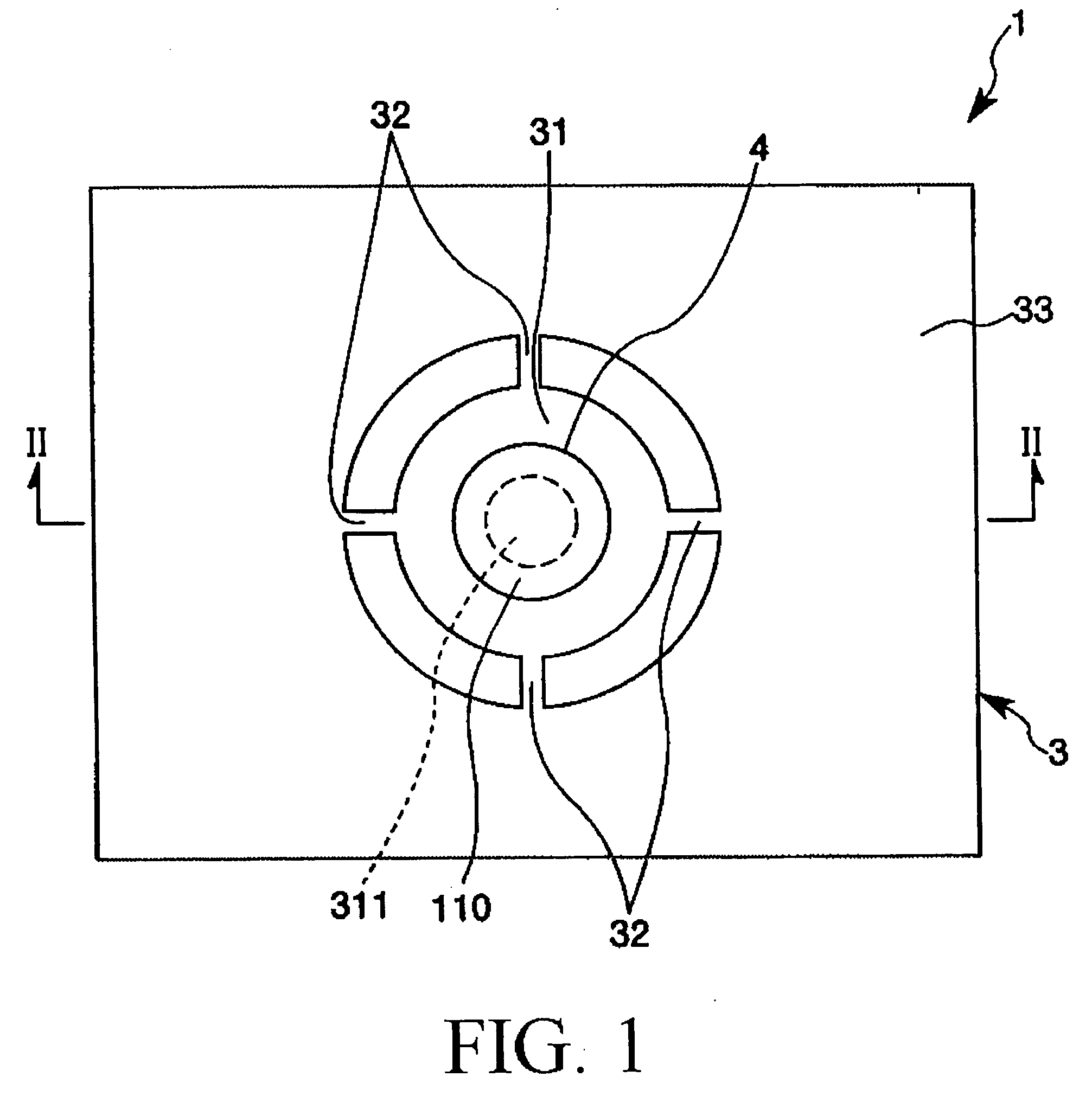
[0078]FIG. 1 is a plan view (top view) showing an optical tunable filter 1 according to a first embodiment of the present invention. FIG. 2 is a cross-sectional view taken along line II-II in FIG. 1. FIG. 3 is a diagram explanatory of an operation of the optical tunable filter 1. In the following description, upper and lower sides in FIG. 2 will be referred to as “upper” and “lower,” respectively.

[0079] For example, the optical tunable filter 1 serves as a device for receiving light and emitting light (coherent light) corresponding to a predetermined frequency. As shown in FIG. 2, the optical tunable filter 1 includes a fixed substrate 2 having a light transmittance, a movable substrate 3 facing the fixed substrate 2, a light-transmittable substrate 4 having a light transmittance, an interference gap 21, and a drive gap 22. The movable substrate 3 has an electric conductivity and a light transmittance. The interference gap 21 and the drive gap 22 are formed between the fixed substr...

second embodiment

[0150] An optical tunable filter according to a second embodiment of the present invention will be described. FIG. 5 is a plan view (top view) showing an optical tunable filter 1001 according to the second embodiment of the present invention. FIG. 6 is a cross-sectional view taken along line VI-VI in FIG. 5. The following description of the optical tunable filter 1001 in the second embodiment is mainly focused on differences between the second embodiment and the first embodiment. Similar portions will not be described repetitively.

[0151] The optical tunable filter 1001 of the second embodiment is different from the optical tunable filter 1 of the first embodiment in that a light-transmittable substrate 4 is bonded to (provided on) a movable portion 31 at a different location than that in the first embodiment. As shown in FIGS. 5 and 6, in the optical tunable filter 1001 of the second embodiment, the light-transmittable substrate 4 is bonded to (provided on) a surface (lower surface...

third embodiment

[0166] An optical tunable filter according to a third embodiment of the present invention will be described. FIG. 8 is a plan view (top view) showing an optical tunable filter 2001 including a movable substrate 3 and a light-transmittable substrate 4 according to the third embodiment of the present invention. FIG. 9 is a cross-sectional view taken along line IX-IX in FIG. 8. FIG. 10 is a diagram explanatory of an operation of the optical tunable filter 2001. In the following explanation, upper and lower sides in FIG. 9 will be referred to as “upper” and “lower,” respectively.

[0167] For example, the optical tunable filter 2001 serves as a device for receiving light and emitting light (coherent light) corresponding to a predetermined frequency. As shown in FIG. 9, the optical tunable filter 2001 includes a first fixed substrate 10 having a light transmittance, a movable substrate 3 facing the first fixed substrate 10, a light-transmittable substrate 4 having a light transmittance, an...


PUM


Abstract

An optical tunable filter has a fixed substrate having a first recess formed therein and a movable substrate bonded to the fixed substrate. The movable substrate includes a movable portion having an opening formed at a location facing the first recess and a support portion for supporting the movable portion so that the movable portion can be displaced. The optical tunable filter also has a light-transmittable substrate bonded to the movable portion, a fixed reflection film formed on a bottom of the first recess, and a movable reflection film formed on a surface of the light-transmittable substrate. The optical tunable filter includes an interference gap formed between the fixed reflection film and the movable reflection film. The optical tunable filter also includes an actuator operable to displace the movable portion relative to the fixed substrate.

Description

CROSS-REFERENCE [0001] The entire disclosure of Japanese Patent Applications No. 2005-021474 and No. 2005-021473 both filed on Jan. 28, 2005 are expressly incorporated by reference herein. BACKGROUND OF THE INVENTION [0002] 1. Field of the Invention [0003] The present invention relates to an optical tunable filter and a method of manufacturing such an optical tunable filter. [0004] 2. Description of the Related Art [0005] There has been known an optical tunable filter for detecting an intensity distribution at each wavelength. The following optical tunable filters have been known in the art. [0006] 1) Filter Formed by Surface Micro-Machining [0007] In a conventional optical tunable filter, the thickness of a variable gap is controlled only by the thickness of a sacrifice layer. When the thickness of a variable gap is controlled by the thickness of a sacrifice layer, the variable gap may have variations in thickness depending upon conditions for deposition of the sacrifice layer. Acc...

Claims


Application Information

Patent Timeline
IPC IPC(8): H01P1/203
CPCG02B26/001G01J3/26G02B5/28
Inventor NAKAMURA, RYOSUKECHUNG, CHANG HO
Owner SANTEC
Why Eureka
Try Eureka