
Tree anchor apparatus and method

Inactive Publication Date: 2006-08-24
SPICER DAVID A
View PDF26 Cites 2 Cited by
  • Summary
  • Abstract
  • Description
  • Claims
  • Application Information

AI Technical Summary

Benefits of technology

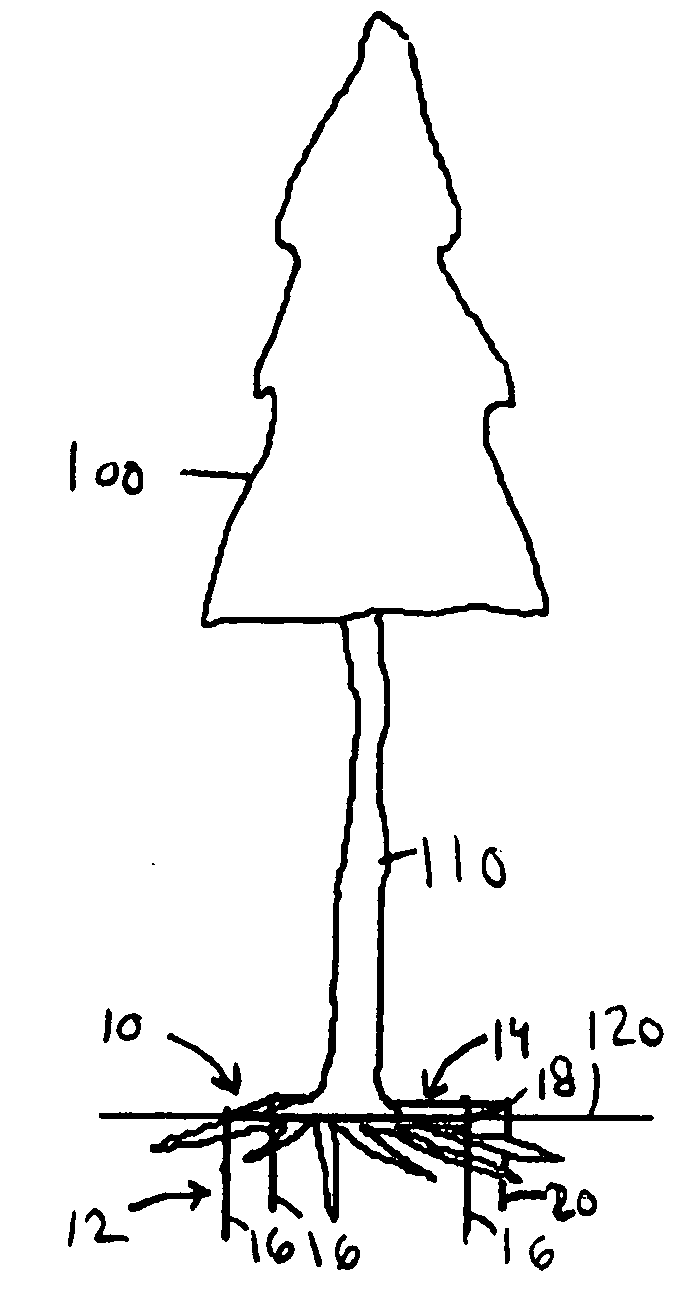
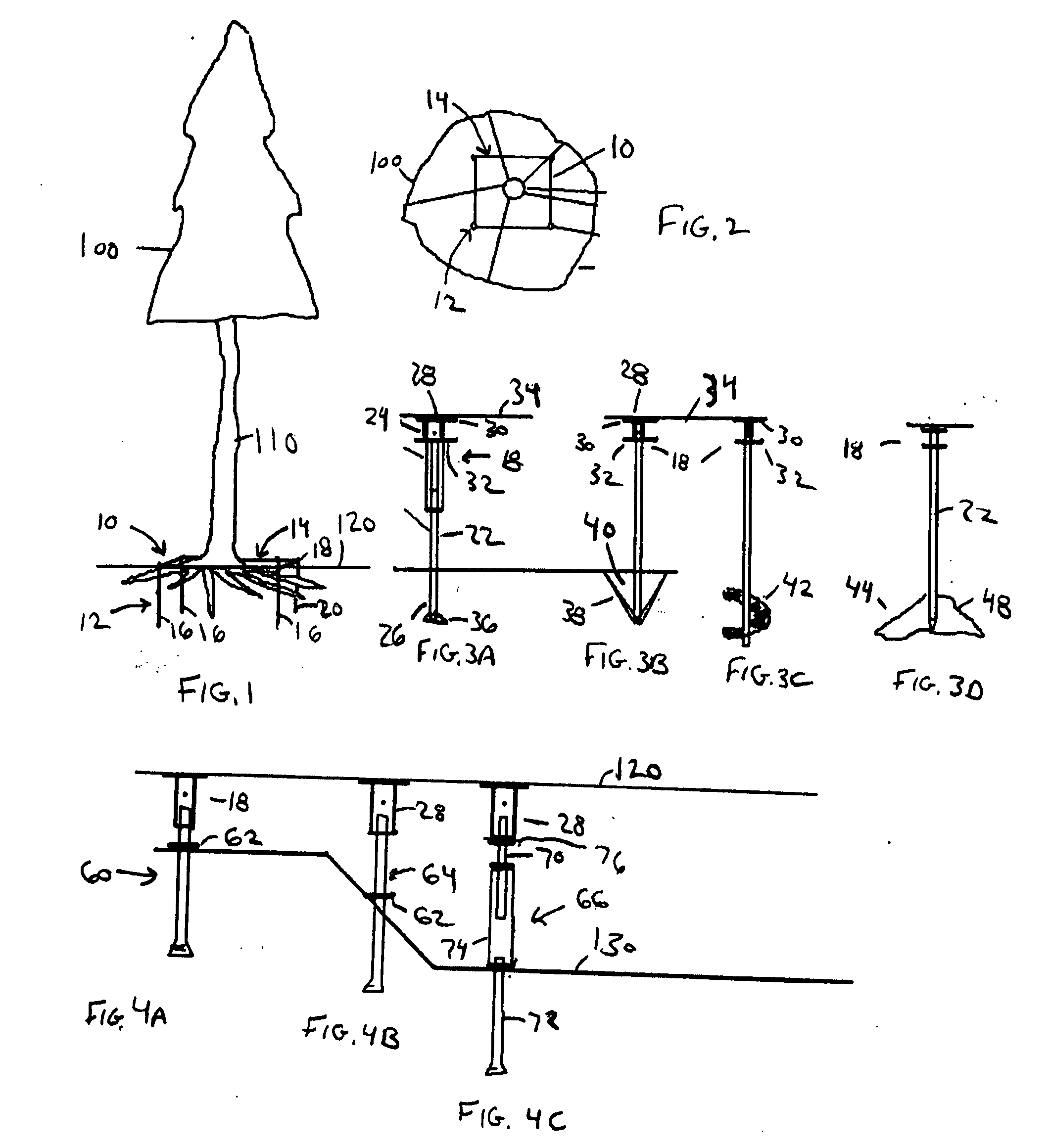
[0011] These and other objects are achieved by the present invention, which is a tree stabilization system and related method. The stabilization system includes a perimeter anchor system and a retention system. The perimeter anchor system is affixable in the underlying soil or rock. The perimeter anchor system includes a plurality of ground anchor assemblies, each terminated at the top thereof by a fixing component positioned at or below the surface of the ground. One or more retention means such as a retaining cable or cables is / are attached to the ground anchor assemblies at the fixing component, preferably but not necessarily, with adjustment means to tighten the retention means when desired. The retaining cables may be detachably connected to the fixing component such as by a bolt or other such detachable connecting means. An eyebolt or other looped structure may also be affixed to the fixing component to optionally retain a means for connecting the ground anchor assemblies to the trunk such as a guy wire. A load distribution means to distribute the downward pressure laterally from the cable across a wider lateral area to the root system, and to minimize root damage over time, may be included. The stabilization system can be positioned around a single tree or a stand of trees to stabilize the entire stand.

Problems solved by technology

It is common for trees to encounter stability problems due to a variety of conditions.
In such situations, it is often the lack of adequate support from the root system that leads to a tree uprooting and tilting or falling.
There are several limitations associated with such conventional devices.
One limitation is that the devices support the trunk, but not the root system.
Another limitation is that the stakes and wires are located above ground level.
They are therefore unsightly and can detract from the appearance of the tree or shrub.
They are also dangerous to pedestrians, children, landscaping equipment and other activities.
For instance, stakes may become loose from regular bumping by a lawnmower or trimmer.
The wire connection can also damage the tree trunk.
Friction can wear away bark and / or the trunk can grow big enough to become constricted by the wire.
A further undesired limitation is that such devices cannot support large trees and are not permanent in nature.
This invention, however, does not address the problem of permanently securing trees or securing mature trees that have been planted for some time.
It also lacks a means of adjusting the tension of the straps after installation.
The Mancini device also cannot be used to secure an entire stand of trees.

Method used


Image

  • Tree anchor apparatus and method
  • Tree anchor apparatus and method
  • Tree anchor apparatus and method

Examples


fourth embodiment

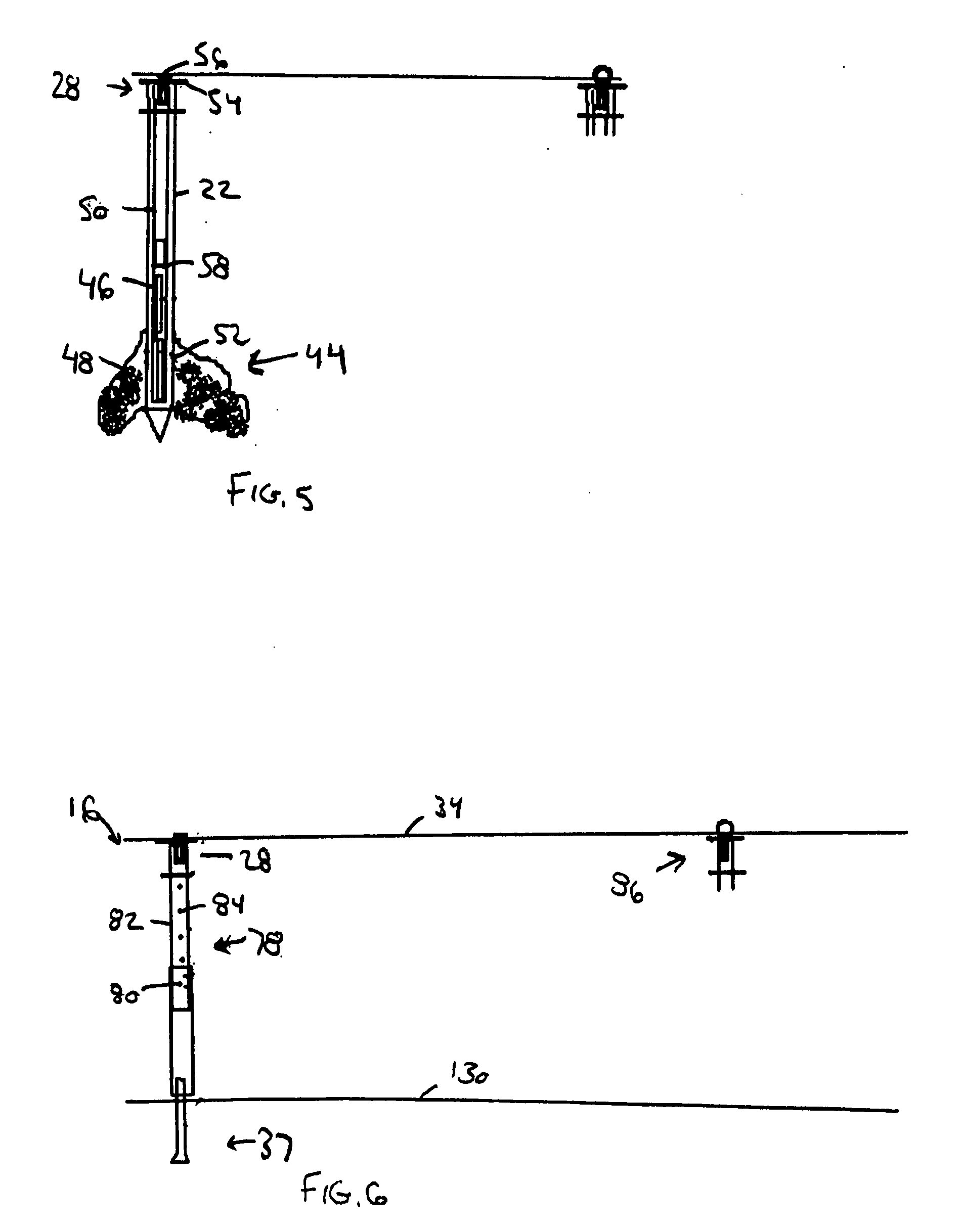
[0032]FIGS. 3D and 5 show the ground anchor assembly 16 with a fourth bottom end 44 and including one or more cartridges 46 or some other means for retaining therein a liquid phase material 48 with the ability to harden, such as resin or concrete. Alternatively, the liquefied material 48 may be displaced through the end of the body 22, which in that instance would be a hollowed body, using pump or injection means applied to the top of the body 22 without an internal cartridge. After first inserting the ground anchor assembly 16 into a hole, an injection means 50 is activated to inject the liquid phase material 48 into the surrounding soil through one or more openings 52 in the bottom end 44, which injected liquid phase material 48 hardens to form a more secure anchoring platform 54. In one example, a plunger 50 is placed in the hollow portion of the bottom end 44 of the ground anchor assembly 16 as the means to force the liquid phase material 44 through the openings 52. In operation...

first embodiment

[0037]FIG. 8 shows a side view of the adjustment means 88 with an adjustment assembly 90 that includes a threaded rod 92. One end of the threaded rod 92 is screwed into the hollow portion of a connecting structure 94 suitable for connecting to a ground anchor assembly 16. The second end of the threaded rod 92 is screwed into a rotatable adjusting structure 96. Rotating the rotatable adjusting structure 96 in one direction decreases the length of the retention system 14 (and thus the tension of the retention system) by drawing the threaded rod 92 further into the rotatable adjusting structure 96 opening. Rotating the rotatable adjusting structure 96 in the other direction has the opposite effect. The end of the rotatable adjusting structure 96 opposite from the end connected to the threaded rod 92 is connected to the cable 34, which, in turn, is suitable for connecting to a ground anchor assembly 16 as previously described.

[0038]FIG. 9 shows a second embodiment of the adjustment mean...


PUM


Abstract

An improved tree stabilization system with a perimeter anchor system of a plurality of individual ground anchor assemblies configured adjacent to the tree or shrub to be supported and a related stabilization method. The tree stabilization system is particularly well suited for use in securing mature trees and stands of trees. As it is adjustable, it may be used for long term stability rather than simply during initial root development. The tree stabilization system includes a retention system that is attached to the perimeter anchor system and runs over the root system and pins the root system to the ground at certain important locations. The ground anchor assemblies are inserted into the ground so that the top end to which the retention system is attached is at or under ground level. The tree stabilization system may include a configuration for anchoring an entire stand of trees and may include a feature for adjusting the tension of the retention system to allow the appropriate amount of downward pressure as conditions change.

Description

BACKGROUND OF THE INVENTION [0001] 1. Field of the Invention [0002] The present invention relates to stabilizing trees and shrubs. More particularly, the present invention relates to an apparatus and method for anchoring the root systems of trees and shrubs to the ground to assist them in remaining upright. Still more particularly, the present invention relates to a system of retention structures above the root system at or just below ground level to retain the root systems. [0003] 2. Description of the Prior Art [0004] It is common for trees to encounter stability problems due to a variety of conditions. For the purposes of the description of the present invention, the word tree includes trees, woody shrubs, and plants. Even the healthiest of trees can tilt or fall over completely due to conditions such as excess moisture in the ground, high winds, the unexpected application of force by an object such as a collision by a car or another tree falling. In such situations, it is often ...

Claims


Application Information

Patent Timeline
IPC IPC(8): A01G17/10
CPCA01G17/04
Inventor SPICER, DAVID A.
Owner SPICER DAVID A
Learn More