System and method for direct passive monitoring of packet delay variation and time error in network packet communications

a network packet and time error technology, applied in the field of time-based network packet communication monitoring protocol, to achieve the effect of greatly improving the test of boundary clocks

Active Publication Date: 2017-10-03
KEYSIGHT TECH SINGAPORE (SALES) PTE LTD
View PDF45 Cites 1 Cited by
  • Summary
  • Abstract
  • Description
  • Claims
  • Application Information

AI Technical Summary

Benefits of technology

[0023]As described herein, passive monitor devices can observe and analyze the packet timing signal traversing between communicating clocks. Based on measurements of time-of-arrival and time-of-departure of packets at the devices and from the time-stamps provided in the packets, the passive monitor device can analyze the network conditions between the monitor and the master. Further, by deploying two passive monitor devices, the sub-network between the monitors can be analyzed and characterized. In addition, by incorporating both passive monitor functions in a single device, testing of boundary clocks is greatly improved. Furthermore, the advantages described herein for testing boundary clocks also apply to testing any other packet timing device having two or more ports (for example, PTP transparent clocks).
[0024]Advantageous features of the disclosed embodiments include, but are not limited to, the following advantages. A passive monitor device can be placed in-line with an actual session between master and slave clocks and is configured to introduce a fixed, symmetric, delay. A passive monitor device can bridge an actual session between master and slave, which is in contrast to prior systems that use additional switches and mirroring ports that tend to add impairments to the timing signal between master and slave. A passive monitor device can quantify timing impairments between the device and the master. Using two monitor devices, the timing impairment introduced by a sub-network can be quantified. Placing both “sides” of impairment measurements in the same equipment eliminates a source of measurement error, namely any synchronization error between devices (e.g., if separate). Further, the sub-network could be a boundary clock, in which case having the capability of measuring both “sides” of a network interface is particularly advantageous.
[0026]In contrast, the passive monitor embodiments described herein can measure the performance of the network in a “live session” using the actual timing packets flowing between master and slave. Because the monitor analyzes the actual packets flowing between master and slave, the monitor has significant advantages. For example, the monitor can analyze the content and timings of the “live session” packets, measure the actual packet rates in use, observe protocol negotiations and handshakes, and analyze protocol mappings. Furthermore, with two or more monitors, it is possible to monitor the same timing flow at multiple points within a network, and this makes it possible to directly measure the impairment introduced by the portion of the network between the two or more monitors.

Problems solved by technology

A passive monitor device can bridge an actual session between master and slave, which is in contrast to prior systems that use additional switches and mirroring ports that tend to add impairments to the timing signal between master and slave.

Method used


Image

  • System and method for direct passive monitoring of packet delay variation and time error in network packet communications
  • System and method for direct passive monitoring of packet delay variation and time error in network packet communications
  • System and method for direct passive monitoring of packet delay variation and time error in network packet communications

Examples


Embodiment Construction

[0040]Systems and methods are disclosed for direct passive monitoring of packet delay variations and time error in network packet communications.

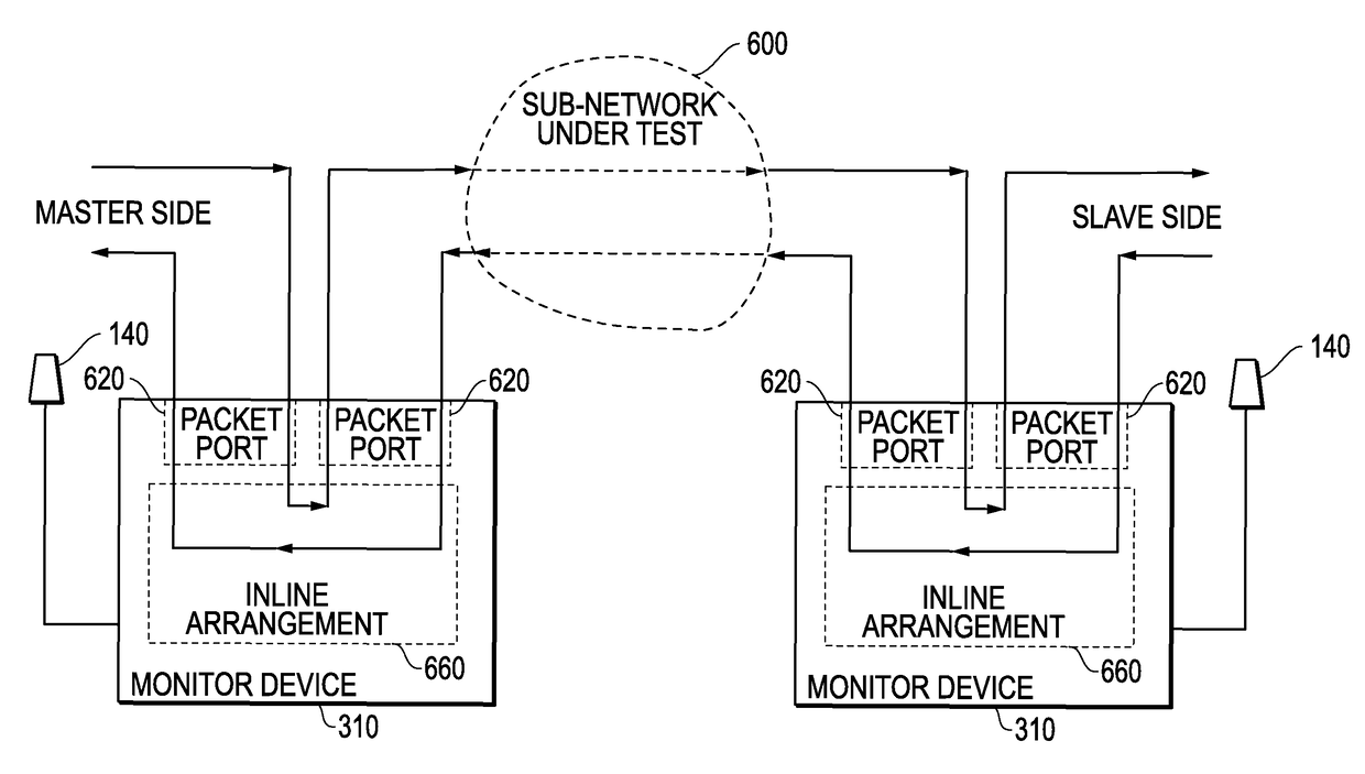
[0041]As described in more detail below, the embodiments disclosed herein monitor the actual packets traversing between slave and master clocks and thereby provide direct results of the actual conditions and do not rely on inference determinations as with prior systems. Certain embodiments described herein provide a bridged configuration or an in-line configuration with fixed, symmetric, delay, providing significant advantages over prior systems. Prior systems often utilize a switch arrangement with a “mirror” port to monitor the packets traversing between the master and slave. The packet delay variation (PDV) introduced by these switch arrangements are additive to, and indistinguishable in nature from, the network PDV between master and slave. Further, testing the behavior of boundary clocks typically requires monitoring traffic on both si...


PUM


Abstract

Systems and methods are disclosed for direct passive monitoring of packet delay variation and time error in network packet communications. Packets traversing between slave and master clocks are monitored to provide direct results of the actual conditions without the need to rely upon inference determinations. Certain embodiments provide tap configurations to monitor packet flows, while certain other embodiments provide in-line configurations to monitor packet flows. Certain further embodiments provide multiple monitoring devices that can be used for passive monitoring purposes, such as passive monitoring to test boundary clock. These multiple monitoring devices can be configured to be within a single or different test instruments. Other variations are also described.

Description

RELATED APPLICATIONS[0001]This application is a continuation application of U.S. patent application Ser. No. 13 / 792,342, filed Mar. 11, 2013, and entitled “SYSTEM AND METHOD FOR DIRECT PASSIVE MONITORING OF PACKET DELAY VARIATION AND TIME ERROR IN NETWORK PACKET COMMUNICATIONS,” which claims priority to U.S. Provisional Patent Application Ser. No. 61 / 650,558, filed May 23, 2012, and entitled “SYSTEM AND METHOD FOR DIRECT PASSIVE MONITORING OF PACKET DELAY VARIATION IN NETWORK PACKET COMMUNICATIONS,” each of which is hereby incorporated by reference in its entirety.TECHNICAL FIELD OF THE INVENTION[0002]This invention relates to the use of timing protocols in network packet communications and, more particularly, to monitoring packet delays associated with network packet communications.BACKGROUND[0003]Packet-based timing methods are becoming essential for delivering timing over packet-switched networks, often referred to as the cloud. In particular, Precision Timing Protocol (PTP) (i.e...

Claims


Application Information

Patent Timeline
Patent Type & Authority Patents(United States)
IPC IPC(8): H04J3/06H04J3/14H04L12/26H04L1/16H04W72/04H04L7/00
CPCH04J3/0635H04J3/14H04L1/1678H04L43/087H04W72/0446H04J3/0667H04J3/0673H04L7/0012H04L43/106
Inventor WEBB, III, CHARLES A.SHENOI, KISHAN
Owner KEYSIGHT TECH SINGAPORE (SALES) PTE LTD
Why Eureka
Try Eureka