V-rake

Active Publication Date: 2006-08-24
BRIDGEVIEW MFG
View PDF33 Cites 14 Cited by
  • Summary
  • Abstract
  • Description
  • Claims
  • Application Information

AI Technical Summary

Benefits of technology

[0015] In accordance with a specific aspect of the invention, the spring assembly comprises a compression spring having first and second ends, a plug fixed to the first end of the spring, an insert fixed to the second end of the spring, the insert has an arm extending from it. A rod that has a first end and a second end is positioned within the compression spring wherein the first end is fixed to the plug and the second end extends out of the second end of the spring through the insert, such that the insert slides freely on the rod. The second end of the rod is adapted to be connected to a mechanism to control its movement. The spring assembly further includes an arm that has first and second ends, the first end is fixed to the rake wheel arm and the second end is pivotally connected to the insert arm, whereby the compression spring permits the rake wheel to move vertically to follow a terrain contour.

Problems solved by technology

Though these rakes have been in use for some time, it has been found that they do not always satisfy the needs of farmers and ranchers in view of their inherent complexity of operation and their weaknesses.
It has also been found that existing mechanisms for adjusting the width of the windrow produced by the rake are ponderous.
When the retainer plate is removed, all of the tines held by the plate become loose and can then fall out of the rake wheel assembly.
This process can be very inconvenient, particularly in the field when the rake wheel assembly is in a vertical position.
Further, it has been found that the material being raked has a tendency to wrap itself on the rake wheel assembly due to the spacing between the tines.
Attempts have been made to remedy this situation by attaching a piece of hard plastic to the tines on the outside of the rake wheel assembly, however this is not found to be fully satisfactory.

Method used


Image

  • V-rake
  • V-rake
  • V-rake

Examples


Embodiment Construction

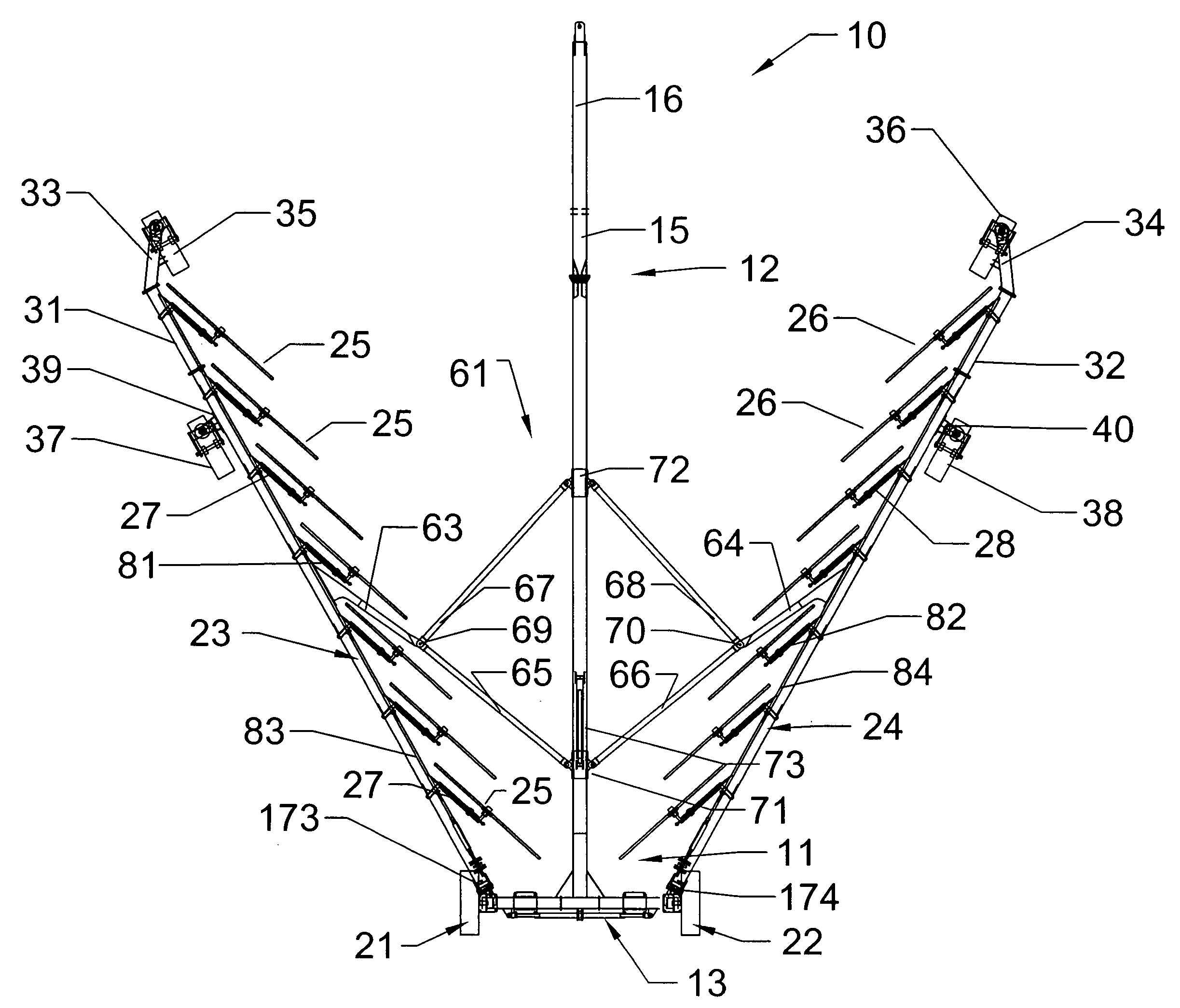
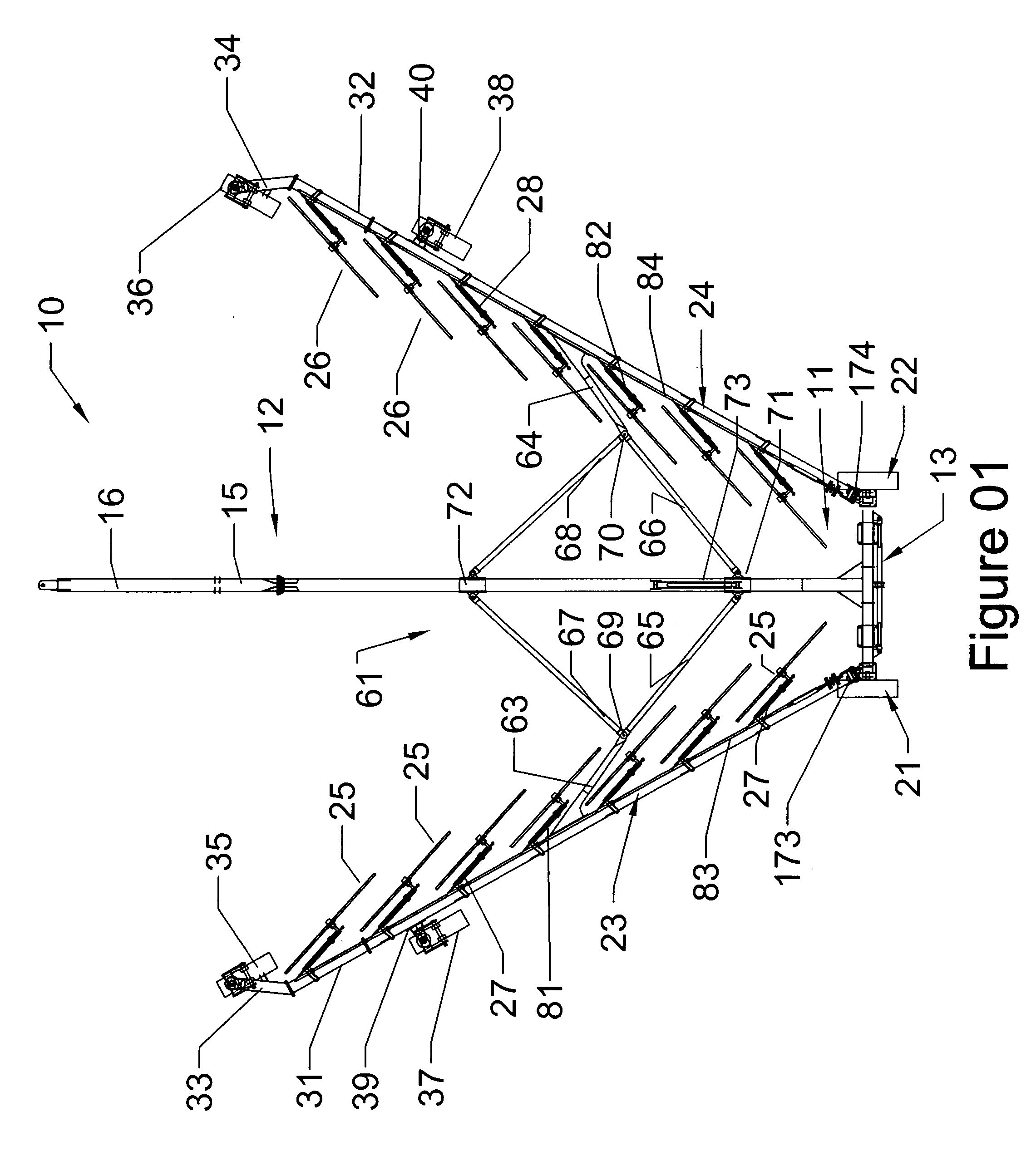
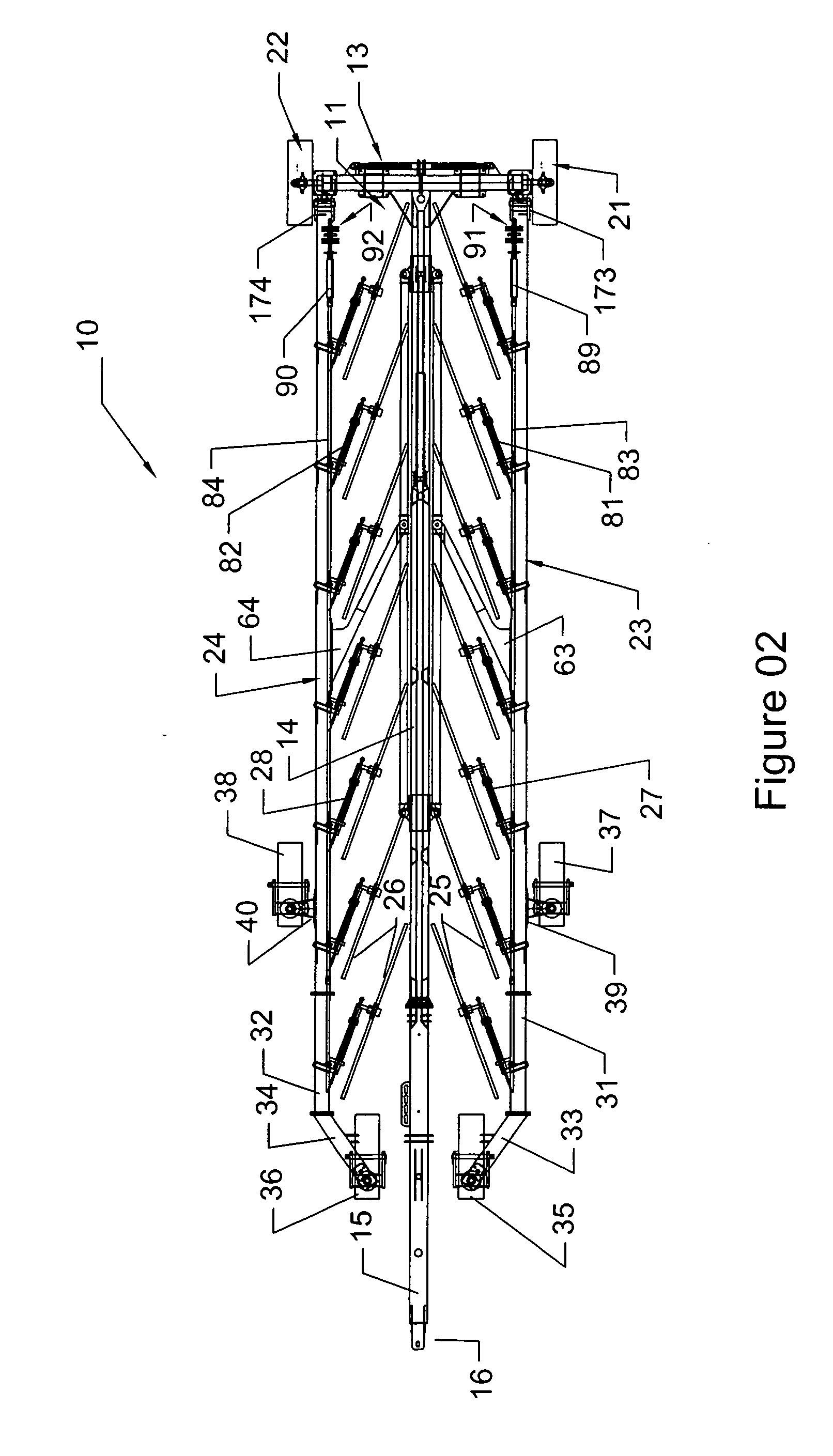
[0047] A V-rake has a pair of rake wheel booms on which rake wheels are mounted, and the size of the V-rake is normally identified by the number of rake wheels that are mounted on the rake wheel booms. For instance, an 8-wheel rake has four rake wheels on each boom, a 10-wheel rake has five rake wheels on each boom, and so on. In order to simplify the manufacturing process for V-rakes while at the same time providing a variety of V-rake sizes, V-rakes having 8, 12 and 16 rake wheels use the same main boom as the V-rakes having 10, 14, and 18 rake wheels, however the booms are each lengthened by a boom extension on which one rake wheel is mounted. However, this type of modular construction is described by way of example only, and other boom arrangements are within the scope of the present invention.

[0048] With reference to the drawings, three V-rake arrangements, namely V-rake 10, V-rake 10, and V-rake 210, will be described. FIGS. 1 and 2 illustrate a top view of V-rake 10, which i...


PUM


Abstract

The V-rake has an elongated tow beam with a front end adapted to be connected to a towing vehicle and a back end fixed to a back section, the back section is supported by a wheel assembly, which may be a set of tandem wheels. The V-rake further includes first and second rake booms each having a front end and a back end pivotally connected to the back section such that the front ends of the booms can be swung between a transport position and an operating position. The front end of each boom has at least one castor wheel for support. The back section is further adapted to controllably change the distance between the back ends of the booms to adjust the width of a resulting windrow. A number of rake wheels are mounted on each of the rake booms on the side of the boom nearest to the tow beam, wherein the rake wheels are adapted to move vertically with respect to the rake boom using a compression spring mechanism. The rake wheel includes a center disk, an outer ring and tines passing through the outer ring with the ends of the tines individually fixed to the center disk, and may further include a windguard.

Description

[0001] This application claims the benefit of U.S. Provisional Patent Application Serial No. 60 / 654,940 filed Feb. 23, 2005 and Serial No. 60 / 662,382 filed Mar. 17, 2005.FIELD OF INVENTION The present invention relates generally to wheel rakes and more particularly to V-rakes. BACKGROUND OF THE INVENTION [0002] V-rakes have been found to be an effective farm implement for gathering cut agricultural materials into windrows. The V-rake generally includes a primary frame, with a front end adapted to be hitched to a tractor and a back end. A pair of rake arms, which are pivotally connected at the back end of the primary frame, are controlled such that they may be positioned adjacent the primary frame in a closed or traveling position or extended in the form of a V in the opened or raking position. The V-rake is supported by a number of rolling wheels mounted on the primary frame and on the rake arms. Further, each rake arm includes a number of rake wheels, which may be raised when the V...

Claims


Application Information

Patent Timeline
IPC IPC(8): A01D78/00
CPCA01D78/146
Inventor HRUSKA, KEVINBARAGAR, DEANHELMECZI, RAYMOND
Owner BRIDGEVIEW MFG
Why Eureka
Try Eureka