Shelf for showcase

a technology for showcases and shelves, applied in the field of shelves for showcases, can solve the problems of high raw material and machining expenses, difficult to keep smoothness, and incur additional expenses, and achieve the effects of reducing molding and raw materials expenses, improving productivity, and simplifying structur

Active Publication Date: 2010-03-25
SEIDAE IND CO LTD
View PDF35 Cites 119 Cited by
  • Summary
  • Abstract
  • Description
  • Claims
  • Application Information

AI Technical Summary

Benefits of technology

[0014]According to the present invention, a single roller unit having a plurality of rollers or a plurality of such the roller units may be simply mounted in the horizontal state by using the connection frames in addition to the fixing frames in the improved structure for surrounding both sides of the single roller unit or the connected plurality of roller units, so that the structure may be simplified, minimizing the expenses in the moldings and the raw materials. Further, machining or finishing work for chilled air ventilation holes is not necessary any more, so that the productivity may be improved and the manufacturing cost thereof may be reduced advantageously.

Problems solved by technology

The prior art shelf for a showcase has, however, problems not only in machining, assembling and continuous connection of such roller units but also in the structure causing high expenses relating to raw materials and machining.
The prior art shelf 1 for a showcase has a disadvantage in the expense since the casing 4 is extruded as a single element incurring high raw material expense and pressed to form the chilled air ventilation holes 44 incurring additional expenses for machining and finishing of the chilled air ventilation holes 44.
In addition, it is difficult to keep smoothness during the extrusion of the casing 4 in the increased size, so that the casing 4 is apt to be distorted.
It is impossible to assemble such the defect casing 4 due to the defect in the extrusion.
Therefore, the casing 4 is disadvantageously limited in the small size to align the roller units 2 only in a single line or two lines.

Method used


Image

  • Shelf for showcase
  • Shelf for showcase
  • Shelf for showcase

Examples


Embodiment Construction

[0026]Now, a shelf for a showcase according to the present invention will be described in more detail in the structure and operation thereof with reference to the accompanied drawings, wherein same component parts as shown in FIG. 11 are referred by the same reference numerals.

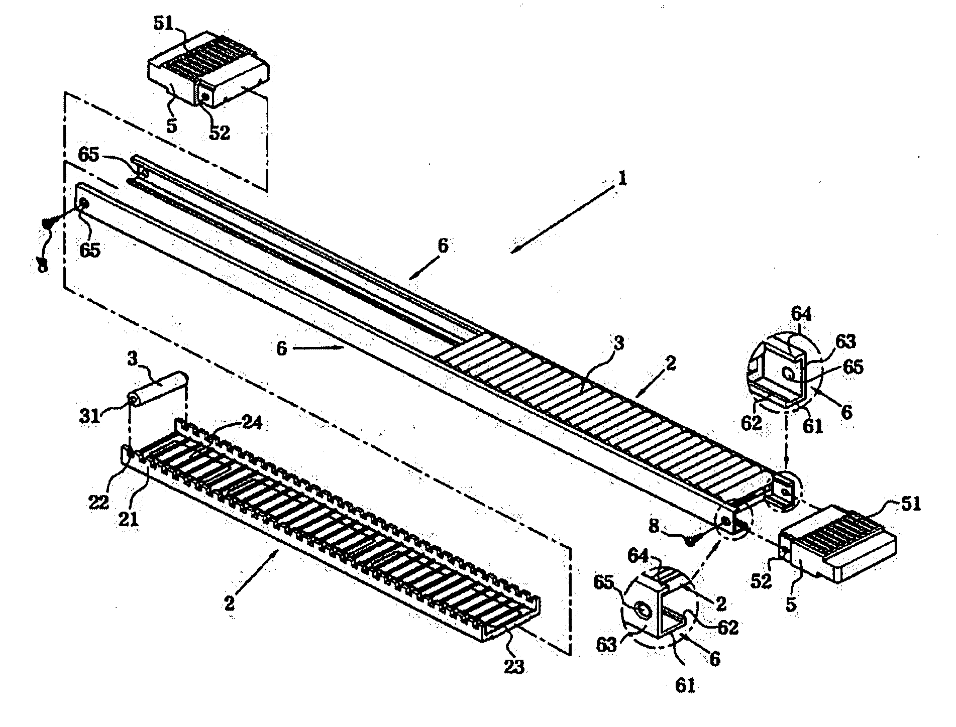
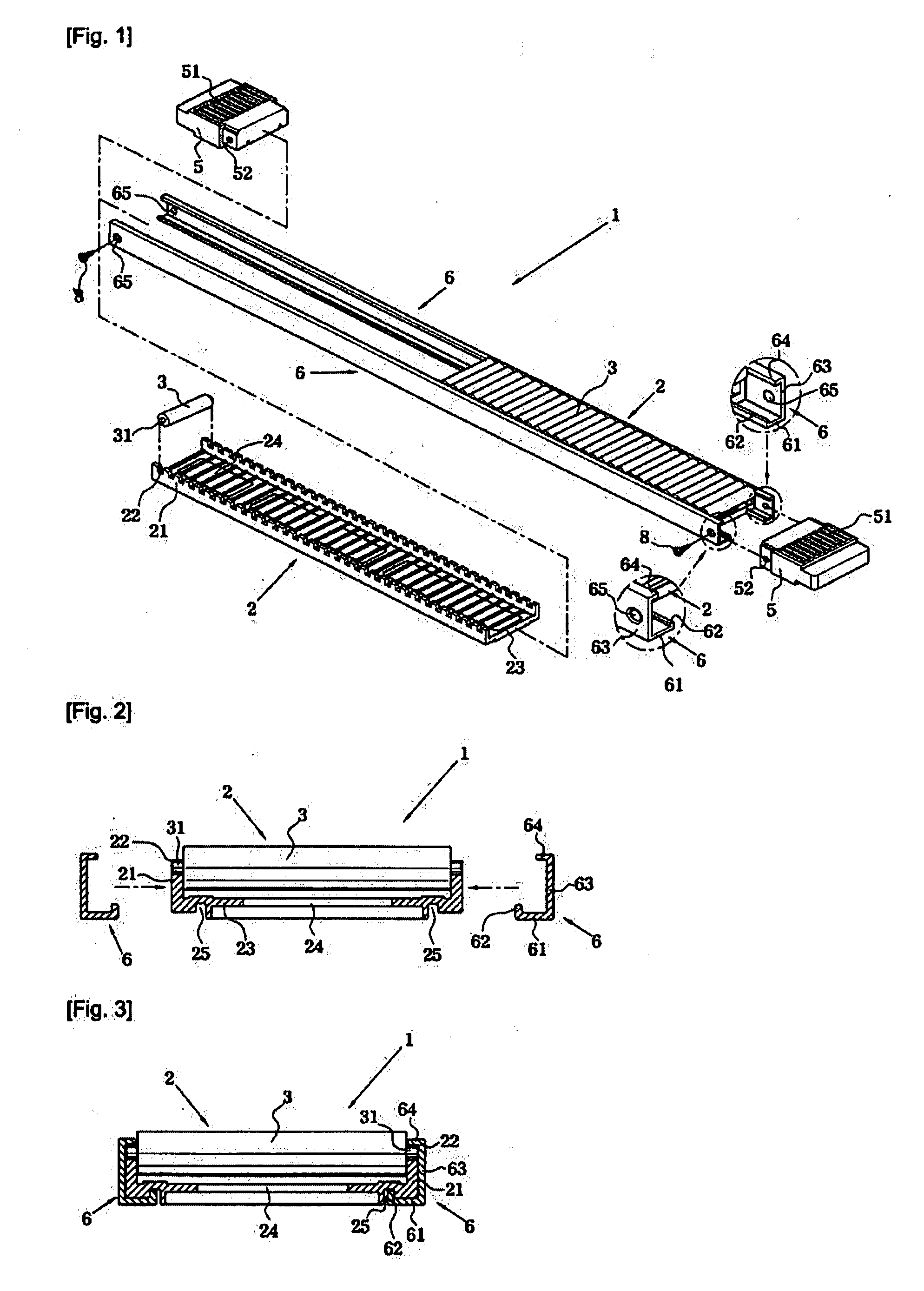
[0027]FIG. 1 is an exploded perspective view showing a shelf for a showcase according to a preferred embodiment of the present invention. Referring to FIG. 1, the shelf 1 is in the structure with a roller unit 2 having a plurality of rollers 3, and end caps 5 and fixing frames 6 coupled with each other. The roller unit 2 has an approximately U-shaped roller plate 23 formed with a plurality of fitting grooves 22 at both side walls 21 to be inserted by mounting shafts 31 protruded at both side ends of the rollers 3 in the same manner with the prior art structure. The end caps 5 are coupled with front and rear ends of the fixing frames 6 in the same manner with the prior art structure, except that the fixing fram...


PUM


Abstract

A shelf for a showcase in which a roller unit is formed with holding grooves on both sides of a bottom surface of a U-shaped roller plate. Fixing frames coupled with the roller plate include a bottom part, formed with a vertical rib to be fitted into the holding groove of the roller plate, and a vertical wall surrounding an outside of the roller plate and formed with a horizontal rib closing opened parts of fitting grooves of the roller plate, so that the fixing frames are mounted on both sides of the roller plate of the roller unit in pair correspondingly to each other. The vertical walls are formed with screw-coupling holes at front and rear ends in accordance with screw holes punched at both side walls of the end caps so as to be integrally coupled together by coupling screws.

Description

TECHNICAL FIELD[0001]The present invention relates to a shelf for a showcase, and more particularly to a shelf for a showcase which is improved in the structure of fixing frames and connection frames for receiving roller units having a plurality of rollers and coupling end caps at front and rear ends.BACKGROUND ART[0002]In general, a shelf for a showcase, which is placed in convenience stores and the like, is to display goods at a front end thereof for a purchaser to distinguish and select the goods conveniently. As the purchaser takes one of the goods from the front end of the shelf, a next one positioned behind the taken one becomes moved to the front end by sliding due to a down-slope from a rear end toward the front end of the shelf which is slant by an inclination angle. The shelf is mounted with a plurality of rollers on a bottom surface contacting the goods for the movement of the next good toward an empty space previously occupied by the first good which is taken by the purc...

Claims


Application Information

Patent Timeline
Patent Type & Authority Applications(United States)
IPC IPC(8): A47F5/00A47F3/14
CPCA47F1/12A47F3/06A47F3/14
Inventor KIM, DEOK RAE
Owner SEIDAE IND CO LTD
Why Eureka
Try Eureka