Optical display interface for electronic tuner for musical instruments

a technology of electronic tuners and interfaces, applied in the field of interfaces for electronic tuners for musical instruments, can solve the problems of inconvenient operation, linear displays do not lend themselves well to various tuning display modes, etc., and achieve the effects of easy detection, quick determination of the effect of manual tuning adjustment, and easy and quick determination

Inactive Publication Date: 2006-08-24
D'ADDARIO
View PDF8 Cites 16 Cited by
  • Summary
  • Abstract
  • Description
  • Claims
  • Application Information

AI Technical Summary

Benefits of technology

[0011] It is an object of this invention to provide an interface for an electronic tuning device for a musical instrument which provides an inexpensive, compact yet easily discernible illuminated dial display which enables a user to readily and quickly determine whether a musical instrument is in tune and to quickly determine the effects of manual tuning adjustment.
[0012] The present invention is an interface for an electronic tuning device which provides a compact, portable but easily discernible display having bi-color light emitting diodes (LEDs) which are arranged in a circular pattern as an illuminated dial display. This arrangement enables a user to readily and quickly determine whether a musical instrument is in tune and to quickly determine the effects of manual tuning adjustment. The interface provides either or both of two major modes of operation, which are a sweep mode and a strobe mode, to afford a readily discernible process for the user to determine when the musical instrument has been properly tuned. The modes can be selected by a preferably combined dual function power switch and display mode selector switch. A calibration reference frequency can be easily changed by pressing a reference frequency switch.

Problems solved by technology

These electronic tuners have linear segmented displays and, thus, are not compact in size.
Also, such linear displays do not lend themselves well to various tuning display modes, such as a “sweep” mode and a “strobe” mode, as the illumination of the segments is not necessarily continuous at the opposite ends of the display.

Method used


Image

  • Optical display interface for electronic tuner for musical instruments
  • Optical display interface for electronic tuner for musical instruments
  • Optical display interface for electronic tuner for musical instruments

Examples


Embodiment Construction

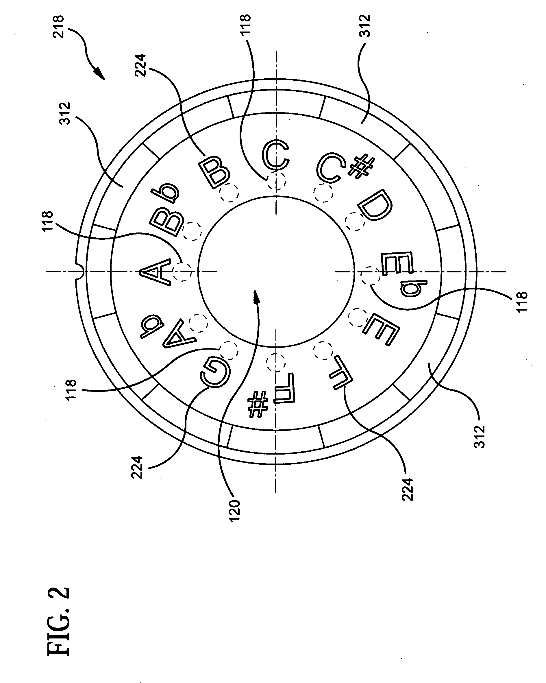
[0045] The present invention is directed to an interface for an electronic tuning device for a musical instrument which provides an inexpensive, compact yet easily discernible illuminated dial display that enables a user to readily and quickly determine whether a musical instrument is in tune and to quickly determine the effects of manual tuning adjustment.

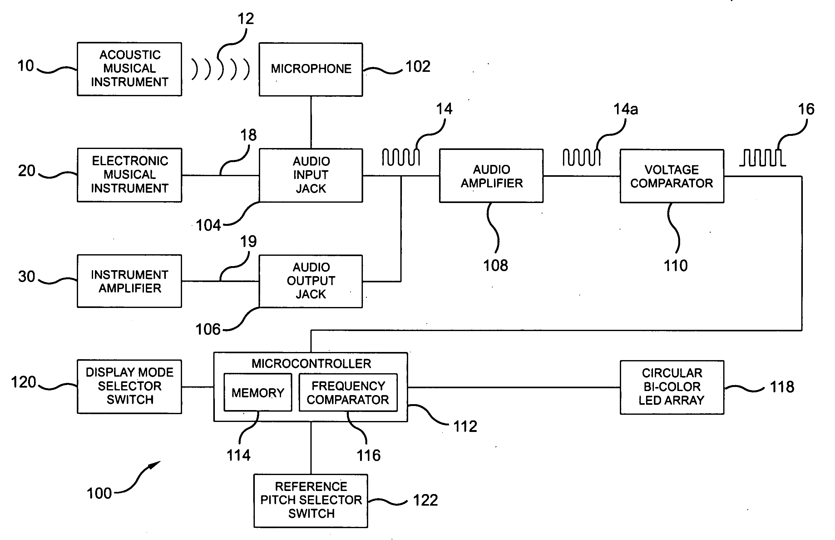
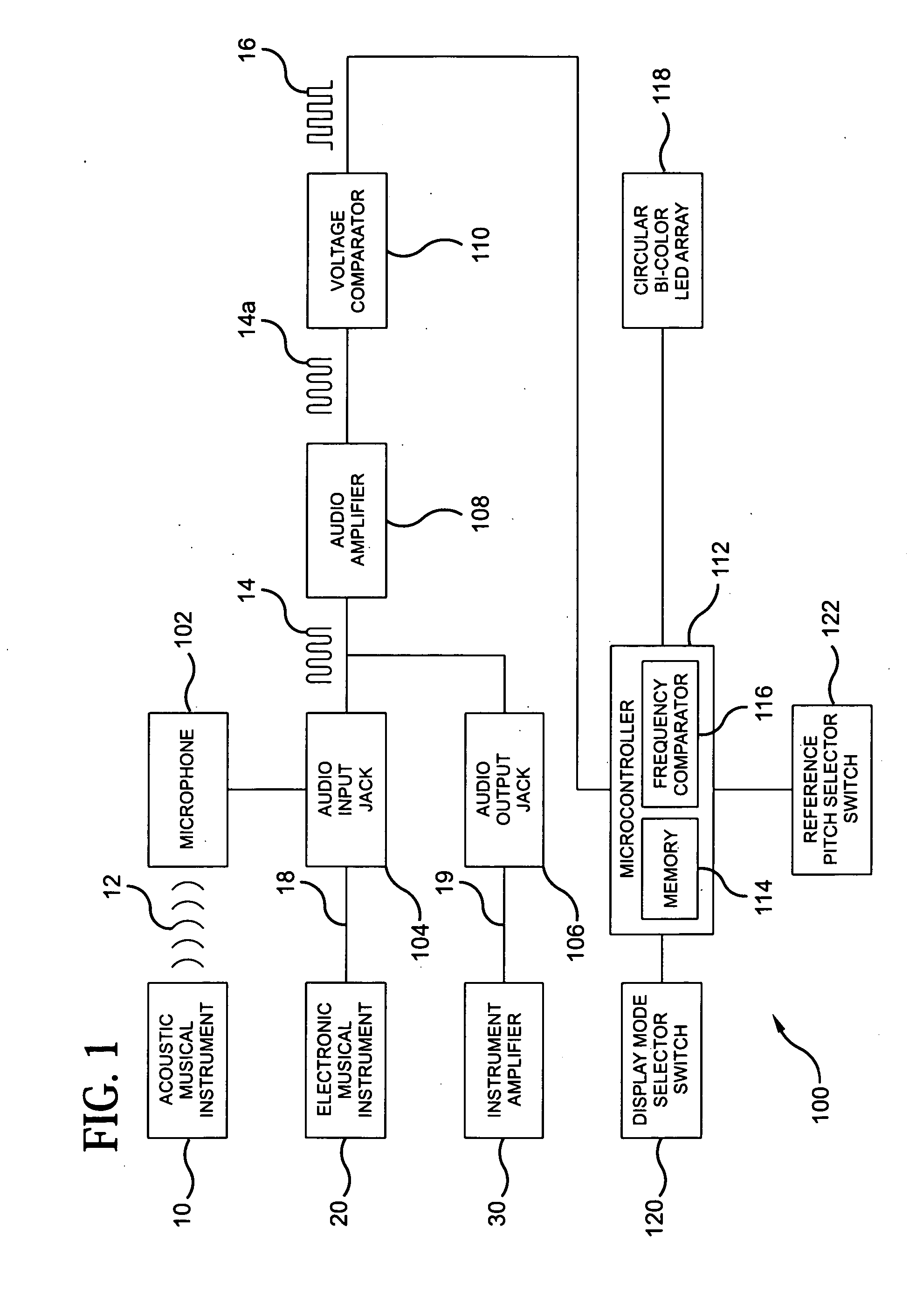
[0046]FIG. 1 is a block diagram of a circuit 100 of an electronic tuner for tuning a musical instrument, which circuit controls the illumination of a display interface connected thereto. The circuit 100 may be used to tune either an acoustic musical instrument 10, such as an acoustic guitar, or an electronic musical instrument 20, such as an electric guitar. When the instrument to be tuned is an acoustic musical instrument 10, a microphone 102, preferably internal to the electronic tuner, receives acoustic waves 12 from the acoustic instrument 10. The microphone 102 acts as a transducer, converting the acoustic waves 12 to an out...


PUM


Abstract

A display interface for an electronic tuner for tuning a musical instrument includes a plurality of spaced apart, separately illuminatable, light emitting diodes (LEDs) situated in a continuous circular array. A cylindrically-shaped light pipe is situated in proximity to the circular array of LEDs. The light pipe has radially extending slits formed therein to define individually illuminatable segments. Each segment of the light pipe is illuminatable by a respective light emitting device. A disc-shaped note dial is situated in proximity to the light pipe and has illuminatable indicia on a surface thereof corresponding to musical notes. The indicia is illuminatable by the light pipe for viewing by a user of the electronic tuner.

Description

CROSS REFERENCE TO RELATED APPLICATION [0001] This application is related to U.S. provisional patent application Ser. No. 60 / 645,671, filed on Jan. 21, 2005, and entitled “Optical Display Interface For Electronic Tuner For Musical Instruments”, the disclosure of which is incorporated herein by reference. This application claims the benefit of priority under 35 U.S.C. 119 to the aforementioned related provisional application.BACKGROUND OF THE INVENTION [0002] 1. Field of the Invention [0003] The present invention generally relates to tuners for musical instruments, and more particularly relates to an interface for an electronic tuner for musical instruments to optically display for a musical note the pitch detected and the relative intonation of the note. [0004] 2. Description of the Prior Art [0005] One of the most basic requirements for a musician is to be sure that his or her musical instrument is “in tune”, meaning that the frequency (or pitch) of the notes produced by the instru...

Claims


Application Information

Patent Timeline
Patent Type & Authority Applications(United States)
IPC IPC(8): G10G7/02
CPCG10G7/02
Inventor D'ADDARIO, JAMES A.WALLACE, HENRY B.
Owner D'ADDARIO
Why Eureka
Try Eureka