System and method for thermal management using distributed synthetic jet actuators

a synthetic jet actuator and actuator technology, applied in the field of thermal management technology, can solve the problems of electromagnetic interference and noise generated by the magnetic-based fan motor, the relative inefficiency of fans in heat removal, and the major challenge of thermal managemen

Inactive Publication Date: 2006-08-24
GEORGIA TECH RES CORP
View PDF99 Cites 65 Cited by
  • Summary
  • Abstract
  • Description
  • Claims
  • Application Information

AI Technical Summary

Benefits of technology

[0015] In some exemplary embodiments, the channel is comprised of one or more tubes connected to an external surface of a wall of the synthetic j

Problems solved by technology

Indeed, thermal management is a major challenge in the design and packaging of state-of-the-art integrated circuits in single-chip and multi-chip modules.
Fans are capable of supplying ample volume flow rate, but there are several distinct disadvantages to using a fan.
Fans are relatively inefficient in terms of the heat removed for a given volume flow rate.
In addition, the use of fans to globally or locally cool a heated environment often results in electromagnetic interference and noise generated by the magnetic-based fan motor.
For this or other reasons, fans may be hindered by long-term reliability.
Mobile applications introduce the added complication of space constraints that might be difficult to achieve with fans, while at the same time increa

Method used


Image

  • System and method for thermal management using distributed synthetic jet actuators
  • System and method for thermal management using distributed synthetic jet actuators
  • System and method for thermal management using distributed synthetic jet actuators

Examples


embodiment 40

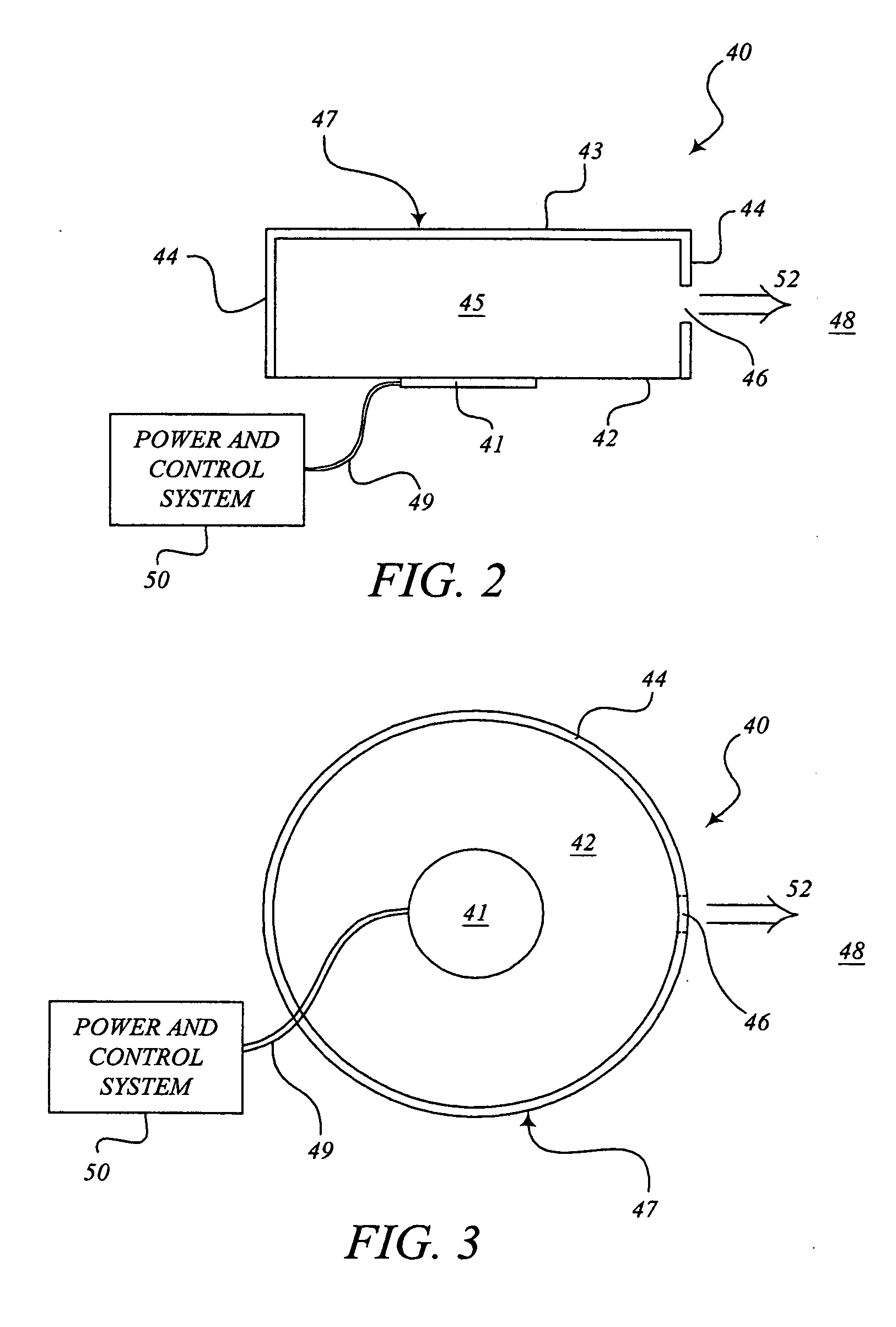
[0044] As noted above, the top wall 43, the flexible diaphragm 42, and the side wall 44 form the housing 47 of a synthetic jet actuator 40 and define a chamber 45 having a volume. The housing 47 of this embodiment 40 comprises the shape of a cylindrical element. This configuration is not required, and the particular configuration has been selected in order to drive home the point that a synthetic jet actuator 40 can take almost any overall shape.

[0045] In this embodiment of a synthetic jet actuator 40, an orifice 46 is formed in a portion of the side wall 44. The orifice 46 fluidically connects the chamber 45 with an ambient fluid 48. The particular size and shape of the orifice 46 is not critical to the present exemplary embodiment 40. By way of example, the orifice 46 could be in the shape of a circular opening, or of a horizontal or vertical slot in the side wall 44.

[0046]FIG. 3 is a plan view of the second exemplary embodiment of a synthetic jet actuator 40, more specifically d...

exemplary embodiment 40

[0056]FIG. 4A depicts one embodiment of a distributed cooling synthetic jet actuator 60. For ease of explanation, the exemplary embodiment of a distributed cooling synthetic jet actuator 60 has been designed as a modified form of the second exemplary embodiment 40. As such, the distributed cooling synthetic jet actuator 60 comprises a housing 47 defining an internal chamber 45. The housing 47 and chamber 45 can take virtually any geometric configuration, but for purposes of discussion and understanding, the housing 47 is shown in cross-section in FIG. 4A to have a rigid side wall 44, a rigid top wall 43, and a diaphragm 42 that is flexible to an extent to permit movement of the diaphragm 42 inwardly and outwardly relative to the chamber 45. A portion of the side wall 44 forms an orifice 46. As above, the orifice 46 can have any geometric shape.

[0057] As with the exemplary embodiment 40 above, the distributed cooling synthetic jet actuator 60 also comprises a power supply and control...

embodiment 80

[0088] As will be recognized by one of ordinary skill in the art, the principle of operation of the multiple actuator distributed cooling apparatus 80 is very similar to the operation of the basic distributed cooling apparatus 60 described above. For example, the tubes 81 of this embodiment 80 act as Helmholtz resonators in the manner described above with regard to the single actuator distributed cooling apparatus 60.

[0089] One common implementation 120 of a multiple actuator distributed cooling apparatus 80 is depicted in FIGS. 11A and 11B. Of course, many other implementations are possible for the apparatus 80, depending on the thermal management requirements of a system and the configuration of the apparatus 80. This exemplary implementation 120 is not limiting on the range of implementations for the apparatus 80. An exemplary implementation is presented merely to better illustrate the features of the present embodiment 80.

[0090] The exemplary implementation 120 involves the use...


PUM


Abstract

One embodiment of the device comprises a device for thermal management. More particularly, one embodiment comprises a synthetic jet actuator (60) and a tube (61). The synthetic jet actuator (60), though not required, typically comprises a housing (47) defining an internal chamber (45) and having an orifice (46) in a wall (44) of the housing (47). The synthetic jet actuator (60) typically also comprises a flexible diaphragm (42) forming a portion of the housing (47). The tube (61) of this exemplary embodiment typically comprises a proximal end (64) and a distal end (65), the proximal end (64) being positioned adjacent to the synthetic jet actuator (60). In this embodiment, operation of the synthetic jet actuator (60) causes a synthetic jet stream (52) to form at the distal end (65) of the tube (61).

Description

TECHNICAL FIELD [0001] The present invention is generally related to thermal management technology and, more particularly, is related to a system and method for cooling heat-producing bodies or components using distributed synthetic jet actuators. BACKGROUND OF THE INVENTION [0002] Cooling of heat-producing bodies is a concern in many different technologies. Particularly in microprocessors, the rise in heat dissipation levels accompanied by a shrinking thermal budget has resulted in the need for new cooling solutions beyond conventional thermal management techniques. Moreover, there is a greatly increased demand for effective thermal management strategies to be used within small handheld devices, such as portable digital assistants (PDA's), mobile phones, portable CD players, and similar consumer products. Indeed, thermal management is a major challenge in the design and packaging of state-of-the-art integrated circuits in single-chip and multi-chip modules. [0003] Traditionally, th...

Claims


Application Information

Patent Timeline
IPC IPC(8): H05K7/20
CPCF04F7/00F15D1/009F15D1/08G06F1/20H01L23/467H05K7/20172Y02T50/166B64C2230/02H01L2924/0002H01L2924/00Y02T50/10
Inventor GLEZER, ARIMAHALINGAM, RAGHAVENDRAN
Owner GEORGIA TECH RES CORP
Why Eureka
Try Eureka