Range-finding system for a portable image reader

a range-finding system and portable technology, applied in the direction of sensors, instruments, cameras, etc., can solve the problems of difficult to determine the direction in which the device must be moved in relation to the target, the operator's difficulty in determining the direction of the device, and the capture of images

Active Publication Date: 2006-08-24
PSION TEKLOGIX
View PDF16 Cites 11 Cited by
  • Summary
  • Abstract
  • Description
  • Claims
  • Application Information

AI Technical Summary

Benefits of technology

[0018] The invention is further directed to a method of operating a portable image-reader. The method includes positioning the image reader before a target, measuring the distance of the portable image reader from the target and comparing the measured distance with an optimal range of reading distances from the target. A first visual indication is provided when the measured distance is within the optimal range, which prompts the triggering of an image acquisition cycle by the image. Alternately, a further visual indication is provided when the measured distance is not within the optimal range, which prompts the operator to move the portable image reader towards a position within the optimal range. The process is repeated until the image acquisition cycle by the image reader is triggered.
[0019] In accordance with another aspect of the invention, the further visual indication provided includes a second visual indication when the measured distance is long of the optimal range, or a third visual indication w

Problems solved by technology

With this method, if the initial operating position is not correct it may be difficult for the operator to determine which direction the device must be moved in order to get into range.
Further, with this method, the operator will perceive that he can only capture an image at the predetermined distance at which the lines or dots converge, even though an acceptable image could potentially be acquired some distance before or beyond that point.
Another drawback to these methods is that it is often difficult to determine which direction the device must be moved in relation to the target.
There are also techniques which use laser diodes to project a crisp, sharp pattern onto the target; however, these methods also do not provide the user with intuitive alignment information with regard to the direction to move the device to place it at the appropriate distance from the target.
The disclosed technique however, is limited to portable lase

Method used


Image

  • Range-finding system for a portable image reader
  • Range-finding system for a portable image reader
  • Range-finding system for a portable image reader

Examples


Embodiment Construction

[0030] For purposes of explanation, specific embodiments are set forth to provide a thorough understanding of the present invention. However, it will be understood by one skilled in the art, from reading this disclosure, that the invention may be practiced without these specific details. Moreover, well-known elements, devices, process steps and the like are not set forth in detail in order to avoid obscuring the scope of the invention described.

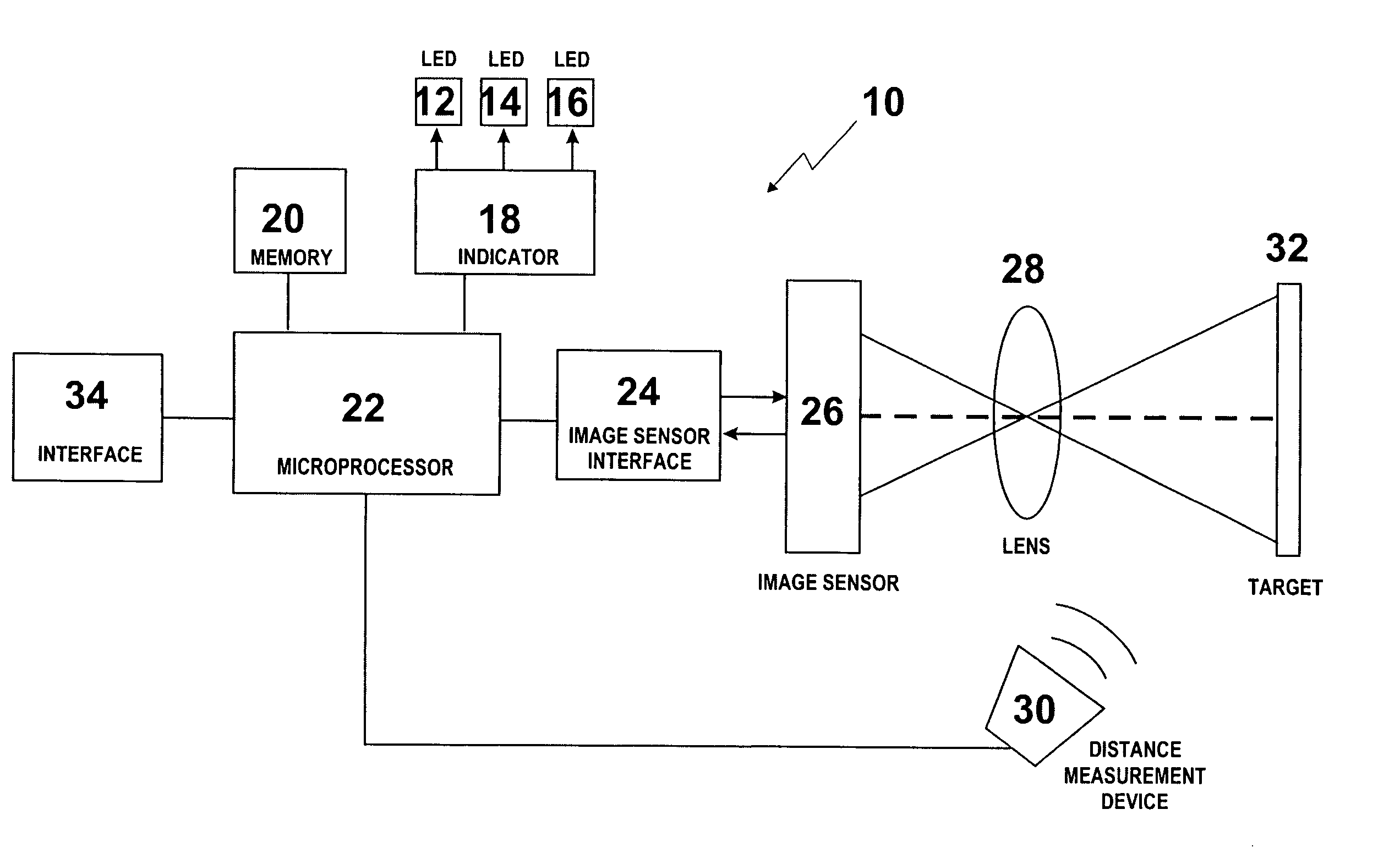
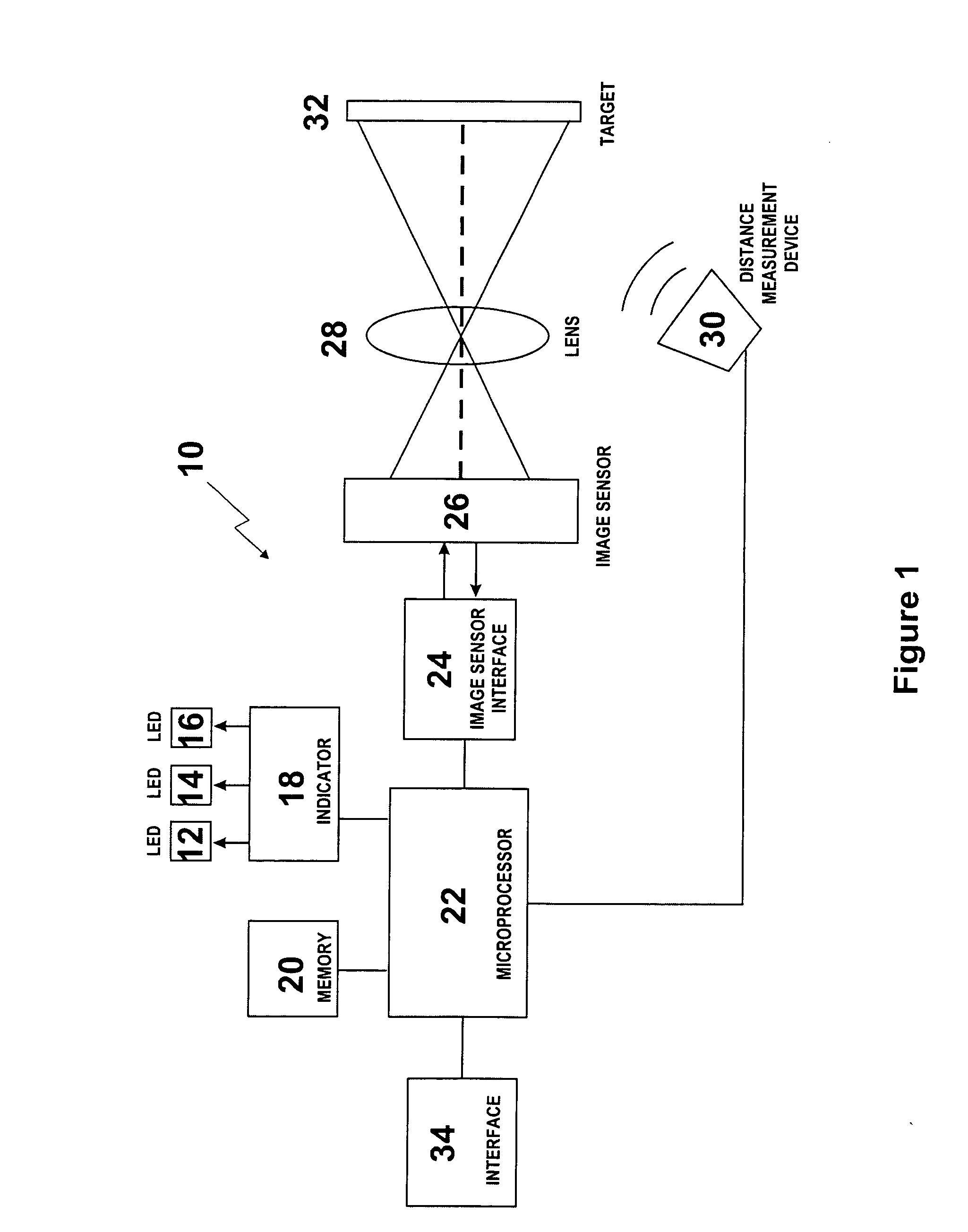
[0031] The invention overcomes problems related to targeting a symbology when using portable imaging devices. The apparatus described provides a quick way of positioning the imaging device within an optimal range of distances from the target.

[0032] In accordance with the present invention, a range-finding system uses a distance-measuring device to determine the distance between a target, such as a label containing a bar code, and an image reading device. An operator receives a visual indication which will assist in positioning the image rea...


PUM


Abstract

A range-finding system for a portable image reader is described. The range-finding system uses a distance-measuring device, such as an ultrasonic transducer, to determine the distance between the reader and a target, such as a label containing a bar code. An operator receives a visual indication which will assist in positioning the image reader within the optimal reading range of the target. The visual indicator may include three LED's of different color or with different blinking rates which will indicate to the operator that the reader is short, long or in the optimal reading range of the reader. In one embodiment, the reader would automatically cycle through an image acquisition or decode sequence when range finder detects that the target is within the optimal reading range of the reader. In another embodiment, the visual indicator will prompt the operator to manually trigger the image acquisition or decode sequence once the reader is positioned within the optimal reading range.

Description

FIELD OF INVENTION [0001] The present invention relates to portable image readers such as barcode readers and more specifically to a range-finding system a portable image reader with. BACKGROUND OF THE INVENTION [0002] Image reading devices of the type that have optimal imaging distances, include a targeting scheme of some kind for aligning the image reader to the target, to be able to position the image reading device at an optimal imaging distance from the target. Most of these techniques project a pattern onto the target from a targeting light source. An aperture and light shaping optics are often used to project a pattern onto the target as an aid to the human operator to correctly position the image reader based on the targeting pattern. [0003] The operator moves the image reader until targeting lines or dots converge at a predefined point, which relates to the point at which an acceptable image can be acquired. An acceptable image may be defined as one that contains sufficient...

Claims


Application Information

Patent Timeline
IPC IPC(8): G06K7/10
CPCG06K7/10851
Inventor PAGE, HARRY
Owner PSION TEKLOGIX
Why Eureka
Try Eureka