Side-view type light emitting device

a technology of light-emitting devices and side-views, which is applied in the direction of printed circuit aspects, sustainable manufacturing/processing, and final product manufacturing, etc., can solve the problems of difficult realization of miniaturization of devices, ineffective transmission of heat generated on the back side of substrates in conventional side-view-type light-emitting devices, and inability to effectively reduce the size of devices, etc., to achieve the effect of transmitting heat generated and easy downsizing

Active Publication Date: 2006-08-24
NICHIA CORP
View PDF4 Cites 25 Cited by
  • Summary
  • Abstract
  • Description
  • Claims
  • Application Information

AI Technical Summary

Benefits of technology

[0010] Accordingly, an object of the present invention is to provide a side-view type light emitting device which is easily be downsized and capable of transmitting heat generated on the substrate surface to the back side of the substrate effectively.

Problems solved by technology

Consequently, there have been problems in a conventional side-view type light emitting device.
Miniaturization of the device has been difficult to realize; and the area of the common terminal electrodes (41a,41b) each connected to the respective through hole can not be widened, so that heat generated on the surface of the substrate can not be transmitted to the back side of the substrate effectively in such a device.

Method used


Image

  • Side-view type light emitting device
  • Side-view type light emitting device
  • Side-view type light emitting device

Examples


first embodiment

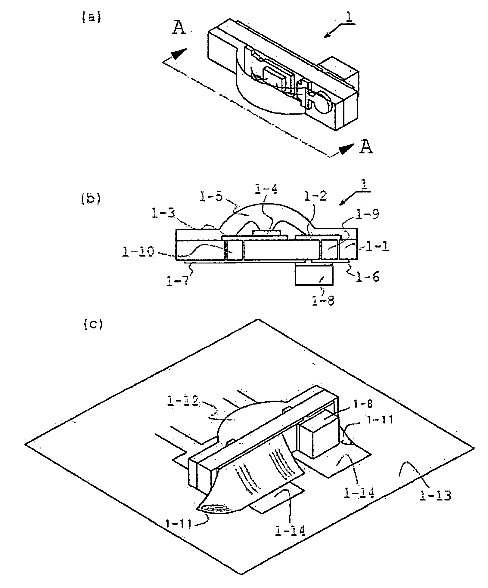
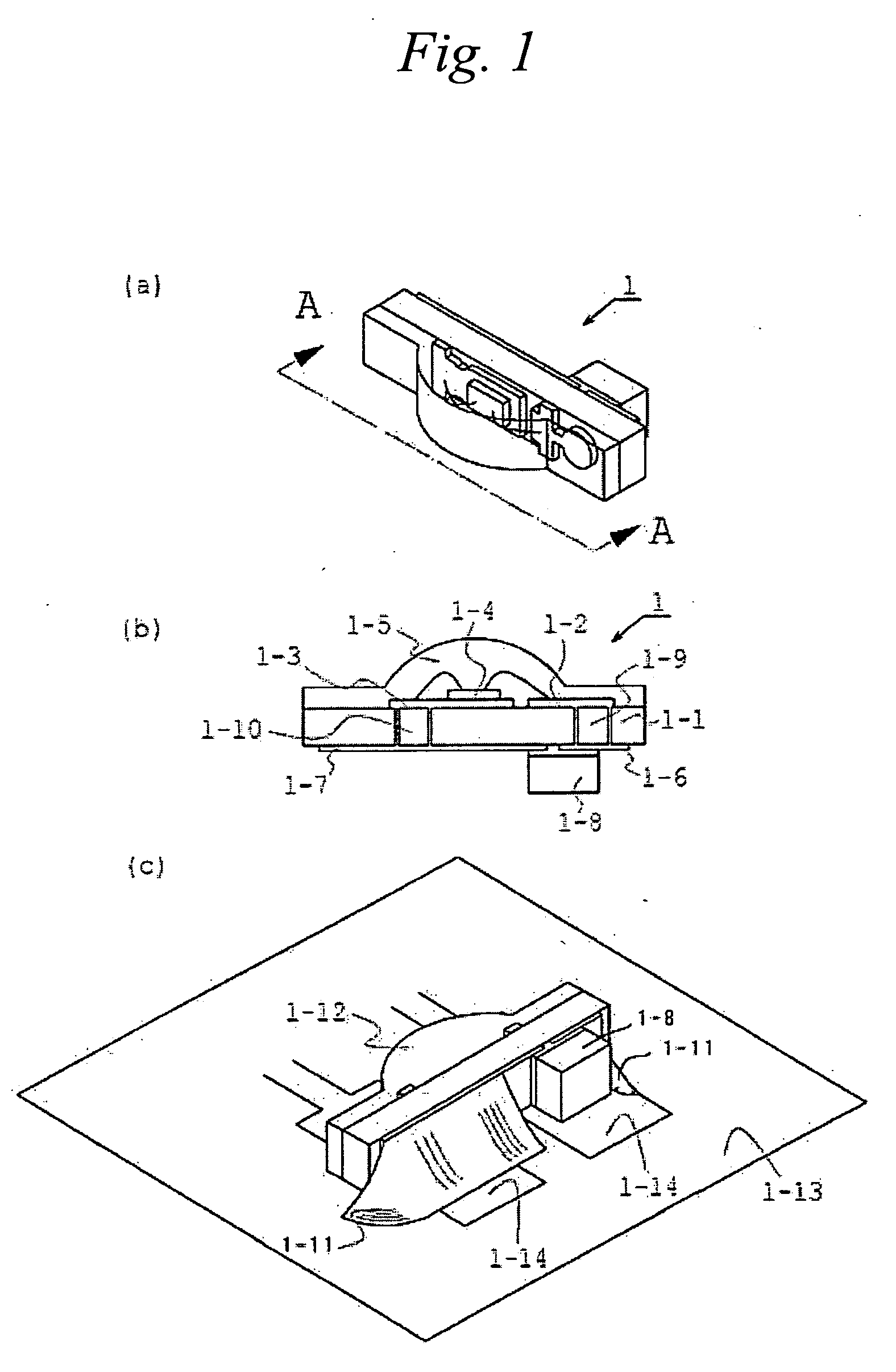
[0026]FIG. 1 shows a side-view type light emitting device 1 according to the present invention. FIG. 1(a) is a perspective view of the side-view type light emitting device 1. FIG. 1(b) is a cross-sectional view taken along line A-A in FIG. 1(a). FIG. 1(c) is a view showing the side-view type light emitting device 1 being mounted on amount substrate 1-13.

[0027] As shown in FIG. 1(c), the side-view type light emitting device 1 of the first embodiment is mounted on the mount substrate 1-13 with the side surface along the longitudinal direction as the mounting surface, and a positive rear surface electrode 1-6 and a negative rear surface electrode 1-7 are connected to respective electrodes for mounting 1-14 on the mount substrate 1-13 through a solder 1-11. The side-view type light emitting device 1 of the first embodiment emits light from a light emitting surface 1-12.

[0028] As shown in FIG. 1(b), the side-view type light emitting device 1 of first embodiment comprising a substrate 1-...

second embodiment

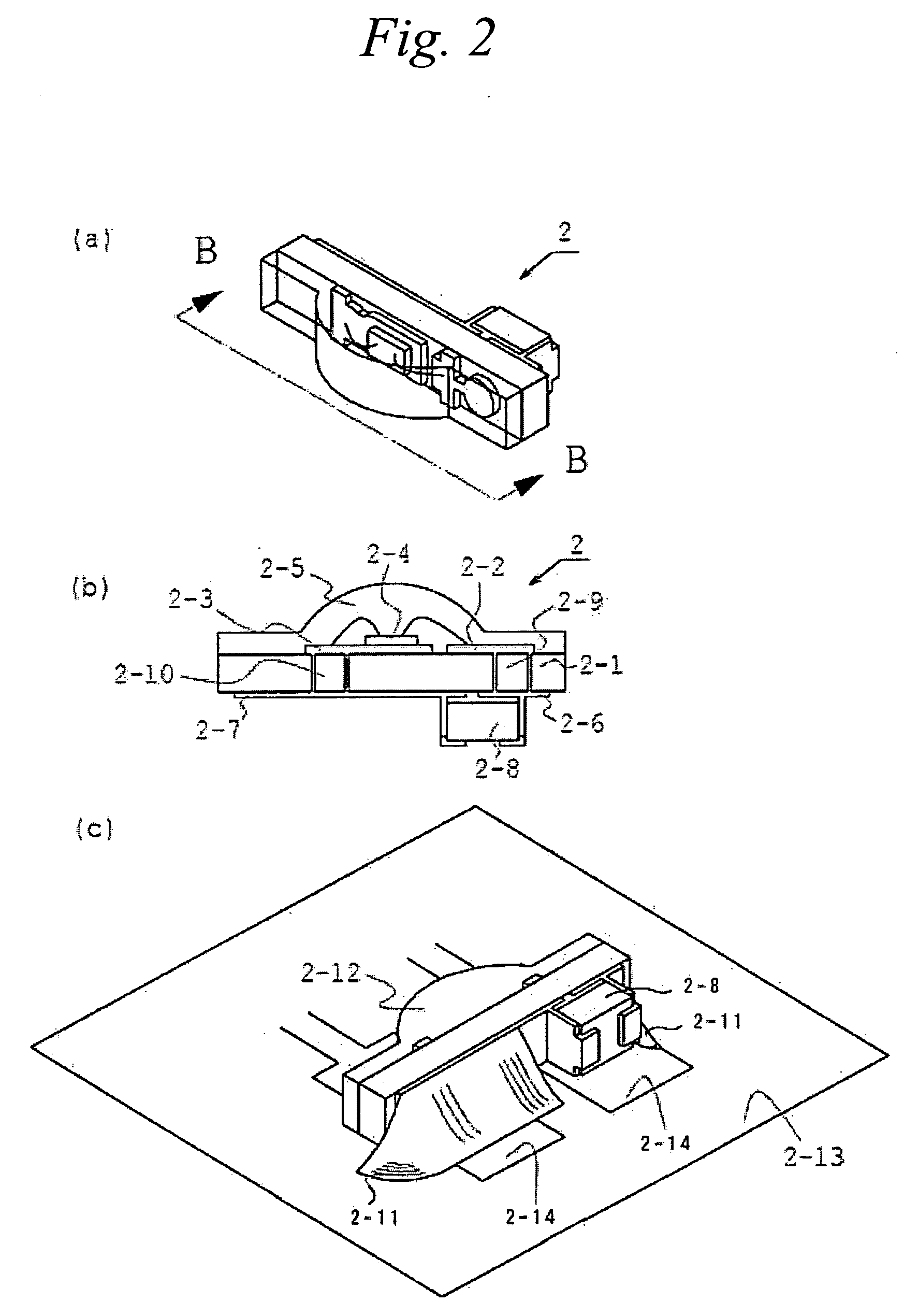
[0051]FIG. 2 shows a side-view type light emitting device 2 according to the present invention. FIG. 2(a) is a perspective view of side-view type light emitting device 2. FIG. 2(b) is a cross-sectional view taken along line B-B in FIG. 2(a). FIG. 2(c) is a view showing the side-view type light emitting device 2 being mounted on a mount substrate 2-13.

[0052] As shown in FIG. 2, in the second embodiment, a rear surface electrodes 2-6 and 2-7 are also disposed on the side surfaces of a short-circuit preventing member 2-8. Thus, according to the side-view type light emitting device 2 of the second embodiment, the areas of the rear surface electrodes 2-6 and 2-7 can be further increased so that heat generated on the surface of the substrate 2-1 can be transmitted to the back side of a substrate 2-1 much more effectively.

third embodiment

[0053]FIG. 3 shows a side-view type light emitting device 3 according to the present invention. FIG. 3(a) is a perspective view of the side-view type light emitting device 3. FIG. 3(b) is a cross-sectional view taken along line C-C in FIG. 3(a). FIG. 3(c) is a view showing the side-view type light emitting device 3 being mounted on a mount substrate 3-13.

[0054] As shown in FIG. 3, in the third embodiment, a short-circuit preventing member 3-8 is disposed on two places instead of one place as in the second embodiment, and the rear surface electrodes are also disposed on the side surfaces of each of the short-circuit preventing member 3-8. That is, a supplemental rear surface electrode may be disposed on a side surface of each of the short-circuit preventing member. Thus, according to side-view type light emitting device 3 of the third embodiment, the areas of the rear surface electrode can be further increased than that in the side-view type light emitting device 2 of the second embo...


PUM


Abstract

A side-view type light emitting device capable of effectively releasing heat generated on the surface of the substrate is provided. The side-view type light emitting device 1 comprising a substrate 1-1, a positive surface electrode 1-2, a negative surface electrode 1-3, a light emitting element 1-4, a sealing member 1-5 sealing the light emitting element 1-4, a positive rear surface electrode 1-6, a negative rear surface electrode 1-7, and a short-cut preventing member 1-8. The positive surface electrode 1-2 and the positive rear surface electrode 1-6 are electrically connected via a first through hole 1-9 and the negative surface electrode 1-3 and the negative rear surface electrode 1-7 are electrically connected via a second through hole 1-10.

Description

[0001] This application claims priority under 35 U.S.C. §119 of Japanese Patent Application No. 2005-41636 filed on Feb. 18, 2005, the contents of which are hereby incorporated by reference. BACKGROUND OF THE INVENTION [0002] 1. Field of the Invention [0003] The present invention relates to a side-view type light emitting device, in particular, to a side-view type light emitting device in which heat generated on the substrate surface is transmitted to a back side of the substrate via a through hole. [0004] 2. Description of the Related Art [0005] A side-view type light emitting device in which heat generated on a substrate surface is transmitted to a back side of the substrate via a through-hole has been proposed in Japanese Laid-Open Patent Publication TOKUKAI No. 2003-78176. This related art type of LED is depicted in FIG. 4. That is, the side-view type light emitting device has a construction in which “. . . two or more LED elements (37,38,39) each having different emission color...

Claims


Application Information

Patent Timeline
Patent Type & Authority Applications(United States)
IPC IPC(8): H01L33/00H01L33/40H01L33/62H01L33/64
CPCH01L25/167H01L33/486H01L33/62H01L2924/09701H05K3/3442H05K2201/099H05K2201/09909H05K2201/10106H05K2201/10454H01L2224/45144H01L2924/00014H01L2224/48091H01L2924/00012Y02P70/50
Inventor TAKINE, KENJIYAMASHITA, RYOHEI
Owner NICHIA CORP
Why Eureka
Try Eureka