Submerged turbine generator

a technology of submerged turbine generator and submerged material, which is applied in the direction of electric generator control, renewable energy generation, greenhouse gas reduction, etc., can solve the problems of difficult to work a long single piece of material to form the shaft, low-priced material having both magnetic properties and high strength is not easily available, etc., to achieve the effect of improving turbine performance, reducing loss and prolonging service li

Inactive Publication Date: 2006-08-24
EBARA CORP
View PDF9 Cites 50 Cited by
  • Summary
  • Abstract
  • Description
  • Claims
  • Application Information

AI Technical Summary

Benefits of technology

[0053] The multiple volute nozzle can also allow the working fluid in the radial direction to form a straight meridional flow running radially. Further, a distance between the outlets of the multiple volute nozzle and the inlets of the runner can be set short. Accordingly, the runner can receive energy of the flow from the multiple volute nozzle with a minimal loss. Therefore, the turbine performance can be improved. Further, since the multiple volute nozzle has a plurality of volute channels, a radial fluid force becomes smaller than a single volute nozzle.
[0054] As described above, the present invention can provide the submerged turbine generator which has advantages including a longer service life, a lower price, and an improved generation efficiency and can meet the need to simplify or eliminate the thrust balancing mechanism.

Problems solved by technology

However, a low-priced material having both magnetic properties and high strength is not easily available.
Further, it is generally difficult to work a long single piece of material to form the shaft.

Method used


Image

  • Submerged turbine generator
  • Submerged turbine generator
  • Submerged turbine generator

Examples


Embodiment Construction

[0090] Embodiments of the present invention will be described in detail below with reference to the drawings.

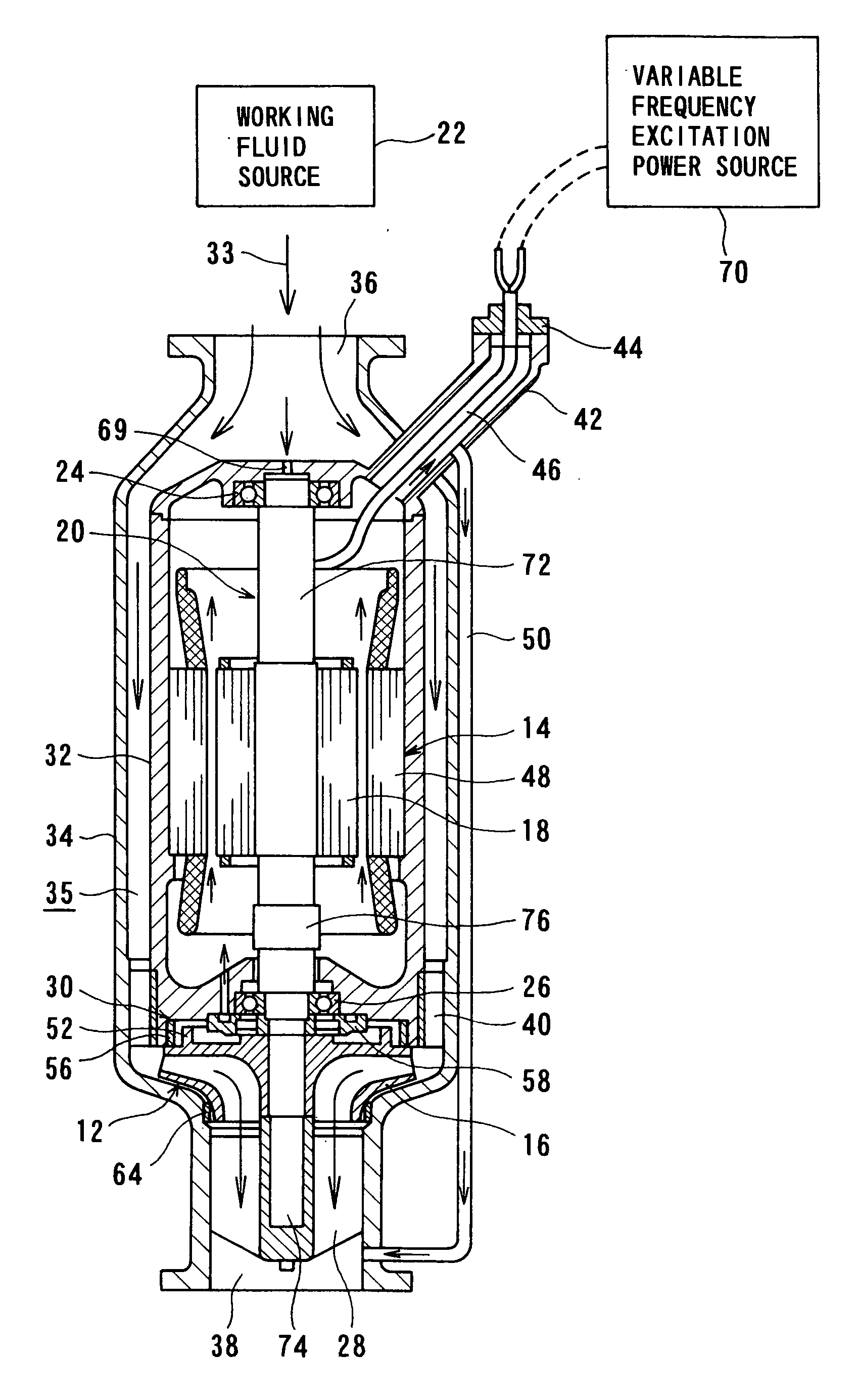
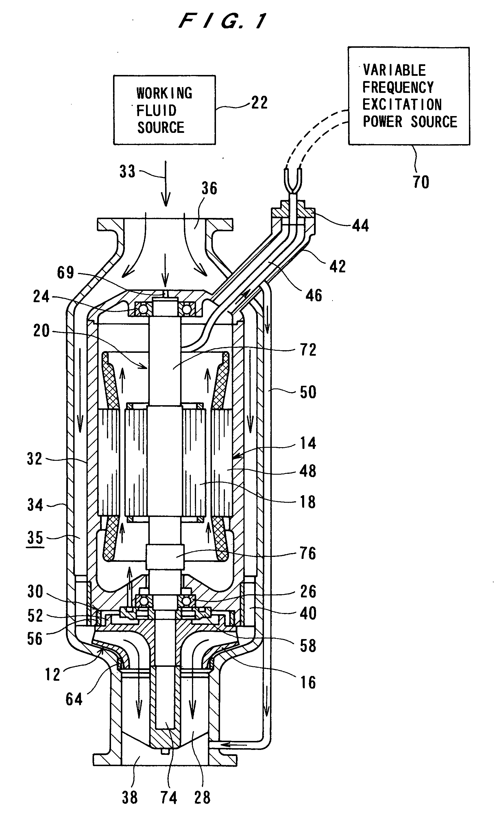
[0091]FIG. 1 is a cross-sectional view showing a so-called vertical submerged turbine generator according to an embodiment of the present invention, and FIG. 2 is an enlarged view showing an essential part shown in FIG. 1. As shown in FIG. 1, the submerged turbine generator comprises a turbine 12 and a generator 14. The turbine 12 has a runner 16, and the generator 14 has a rotor 18. The runner 16 and the rotor 18 are fixed to a shaft 20. In this embodiment, a working fluid, which is used for rotating the turbine 12 to generate electric power and used for cooling the generator 14, is a non-electrical-conductive fluid containing a liquefied low-temperature gas. Examples of such a working fluid include liquefied natural gas, liquefied methane gas, liquid ethylene gas, liquid petroleum gas, liquid nitrogen, and similar liquid hydrocarbon. A working fluid source 22 stores a desi...


PUM


Abstract

A submerged turbine generator is operated by a working fluid, such as liquid nitrogen, liquefied natural gas, or liquid ethylene, to generate electric power. The submerged turbine generator includes a shaft, a casing, a turbine having a runner fixed to the shaft, a generator having a rotor fixed to the shaft and a stator surrounding the rotor, and bearings for rotatably supporting the shaft. The runner is rotated integrally with the shaft by the pressure of the working fluid introduced into the casing. The shaft includes at least two members.

Description

BACKGROUND OF THE INVENTION [0001] 1. Field of the Invention [0002] The present invention relates to a submerged turbine generator, and more particularly to a submerged turbine generator which is operated by a working fluid selected in advance. [0003] 2. Description of the Related Art [0004] There has been known a submerged turbine generator comprising a turbine and a generator. Generally, a low-temperature fluid having a high pressure, such as liquid nitrogen, liquefied natural gas, or liquid ethylene, is used as a working fluid to rotate the turbine. The torque of the turbine rotates a rotor of the generator to thereby generate electric power. The generator is submerged in the working fluid (i.e., the low-temperature fluid) so as to be cooled by the working fluid. [0005] This type of submerged turbine generator generally comprises a turbine fixed to a shaft, a generator having a rotor and a stator, and a housing in which the generator is housed. The housing is accommodated in a ca...

Claims


Application Information

Patent Timeline
Patent Type & Authority Applications(United States)
IPC IPC(8): F03B13/00
CPCF03B13/10F05B2210/10F05B2240/97Y02E10/22Y02E10/223Y02E10/226Y02E10/20
Inventor HONDA, SHUICHIROMATSUMURA, MASAO
Owner EBARA CORP
Why Eureka
Try Eureka