Display device

a display device and display luminance technology, applied in the field of display devices, can solve problems such as deterioration of contrast, and achieve the effect of enhancing display luminance and improving contrast characteristics

Inactive Publication Date: 2006-08-24
TOSHIBA MATSUSHITA DISPLAY TECH
View PDF10 Cites 30 Cited by
  • Summary
  • Abstract
  • Description
  • Claims
  • Application Information

AI Technical Summary

Benefits of technology

[0014] The present invention has been made in consideration of the above-described problems, and the object of the invention is to provide a display device that includes self-luminous elements and is capable of improving contrast characteristics and enhancing display luminance.

Problems solved by technology

Besides, when external light is incident in a state in which the light-emitting layer is caused to produce light, such external light appears on the display screen and the contrast deteriorates.
This problem is conspicuous in a light environment, that is, in a condition in which external light is intense.

Method used


Image

  • Display device
  • Display device
  • Display device

Examples


embodiments

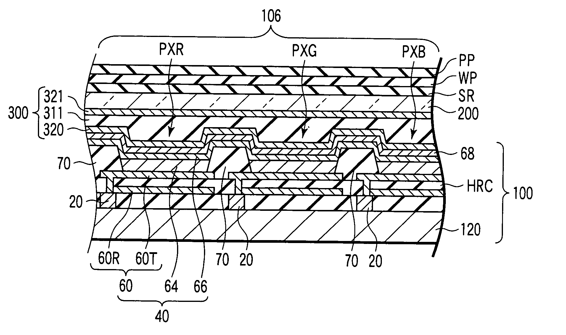
[0084] As is shown in FIG. 7, an organic EL element 40 including a reflective film 60R and an organic active layer 64 was disposed on a wiring substrate 120 and sealed. Then, a selective reflection layer SR, a ¼ wavelength plate WP and a polarizer plate PP were successively disposed from the organic active layer 64 side, and thus a display device was fabricated. For the purpose of simplicity, FIG. 7 depicts only the polarizer plate PP, ¼ wavelength plate WP, selective reflection layer SR, organic active layer (light-emitting layer) 64, reflective film 60R and wiring substrate 120 provided with the organic active layer (light-emitting layer) 64. Depiction of other structural elements is omitted.

[0085] The selective reflection layer SR was formed such that a cholesteric liquid crystal polymer (manufactured by BASF) functioning as a first reflection layer, a cholesteric liquid crystal polymer (manufactured by BASF) functioning as a second reflection layer and a cholesteric liquid crys...


PUM

PropertyMeasurementUnit
reflectanceaaaaaaaaaa
thicknessaaaaaaaaaa
thicknessaaaaaaaaaa

Abstract

When a peak wavelength of light emerging from a light-emitting layer is λp(k) (k=1, 2, . . . , m in an order from a smallest wavelength), the peak wavelength λp(k) is less than a value ne(k)P(k) that is obtained by multiplying an extraordinary-ray refractive index ne(k) of a selective reflection layer that forms each selective reflection region by a helical pitch P(k), and is greater than a value no(k)P(k) that is obtained by multiplying an ordinary-ray refractive index no(k) by the helical pitch P(k). A relationship, ne(k−1)P(k−1)<no(k)P(k), is established between the selective reflection layers that form the selective reflection regions.

Description

CROSS REFERENCE TO RELATED APPLICATIONS [0001] This is a Continuation Application of PCT Application No. PCT / JP2004 / 015731, filed Oct. 22, 2004, which was published under PCT Article 21(2) in Japanese. [0002] This application is based upon and claims the benefit of priority from prior Japanese Patent Application No. 2003-364825, filed Oct. 24, 2003, the entire contents of which are incorporated herein by reference.BACKGROUND OF THE INVENTION [0003] 1. Field of the Invention [0004] The present invention relates to a display device, and more particularly to a display device including a circular polarizer plate and self-luminous elements capable of achieving a high contrast. [0005] 2. Description of the Related Art [0006] In recent years, an organic electroluminescence (EL) element, which is a typical self-luminous element capable of being included in a display device, has attracted special attention, since an organic light-emitting material that is applied to the organic EL element ha...

Claims


Application Information

Patent Timeline
Patent Type & Authority Applications(United States)
IPC IPC(8): G02F1/1335G09F9/00G09F9/30H01L27/32H01L51/52H05B33/12
CPCH01L27/3244H01L51/5281H01L51/5237H10K59/12H10K50/846H10K50/8426H10K50/86H05B33/22H05B33/24
Inventor HISATAKE, YUZO
Owner TOSHIBA MATSUSHITA DISPLAY TECH
Why Eureka
Try Eureka