Shock absorber bearing for a timepiece

a technology of shock absorber bearing and timepiece, which is applied in the direction of mechanical clocks, instruments, and difficult adjustment, can solve the problems of adversely affecting the chronometric qualities of the timepiece, re-centring errors can occur, and the timepiece is difficult to adjust, so as to achieve a wider range of manufacturing tolerances

Active Publication Date: 2006-08-24
ETA SA MFG HORLOGERE SUISSE
View PDF11 Cites 24 Cited by
  • Summary
  • Abstract
  • Description
  • Claims
  • Application Information

AI Technical Summary

Benefits of technology

[0008] It is thus an object of the present invention to overcome the aforecited drawbacks of the prior art by providing a shock absorber bearing comprising a pierced stone and an endstone assembled in a setting susp

Problems solved by technology

In this construction it is very difficult to adjust the compression force of spring 10 and the optimum angle of the complementary inclined planes 7, 7a; 8, 8a at the same time, taking account also of the friction coefficient between said inclined planes, such that re-centring errors can occur after a lateral shock.
This obviously has the drawback of adversely affecting the chronometric qualities of the timepiece.
The presence of the two springs making th

Method used


Image

  • Shock absorber bearing for a timepiece
  • Shock absorber bearing for a timepiece
  • Shock absorber bearing for a timepiece

Examples


Embodiment Construction

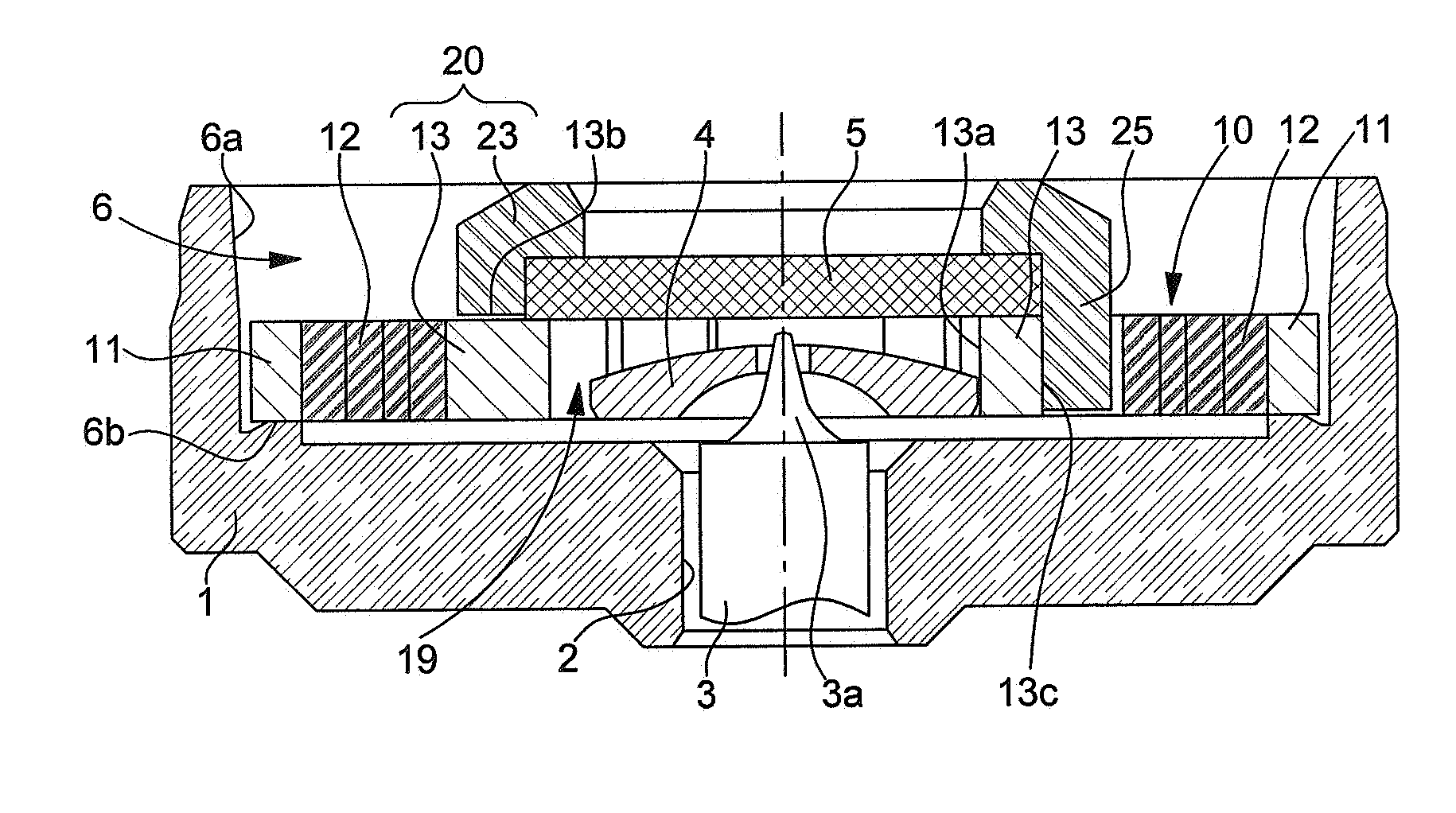
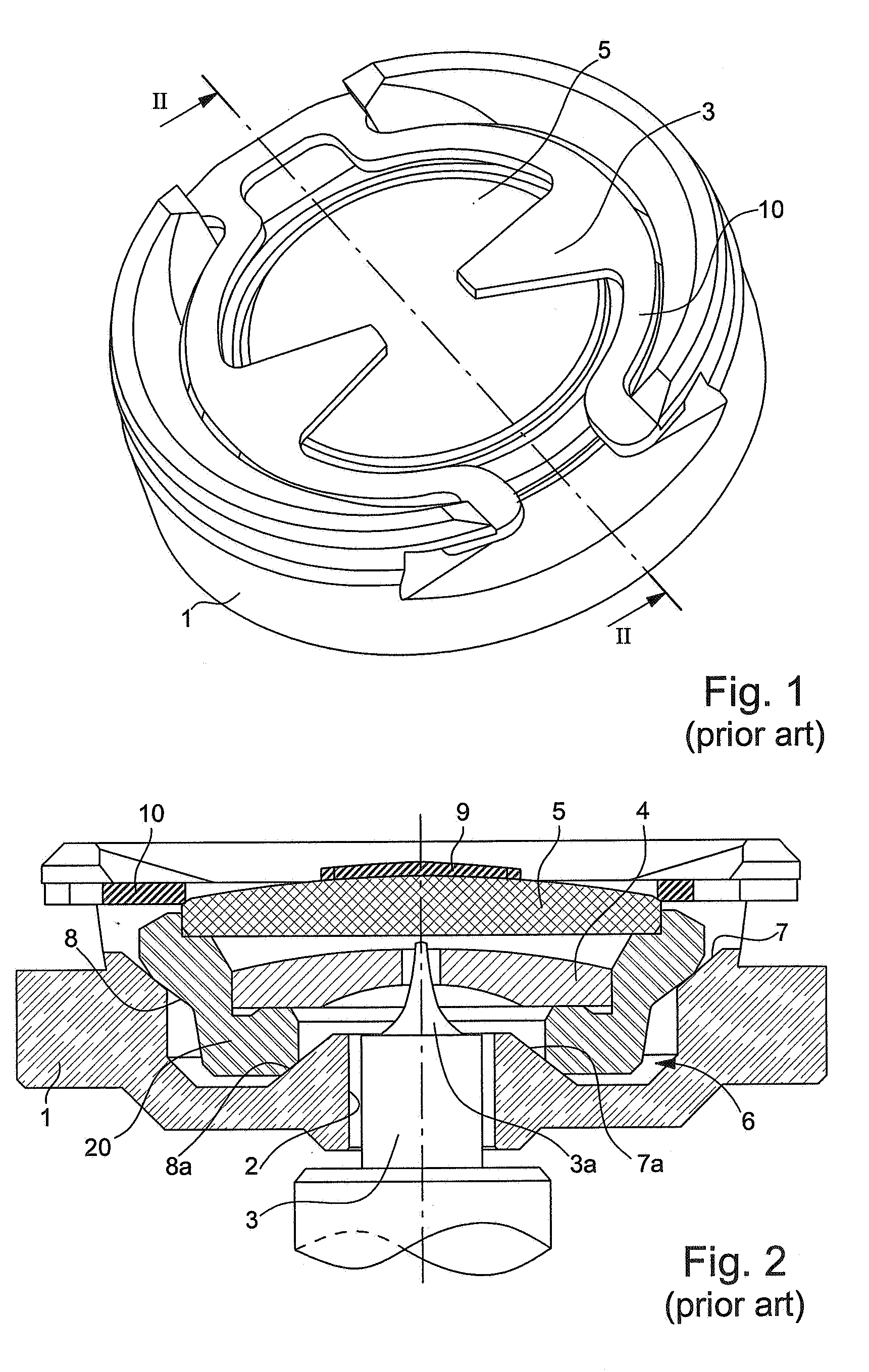
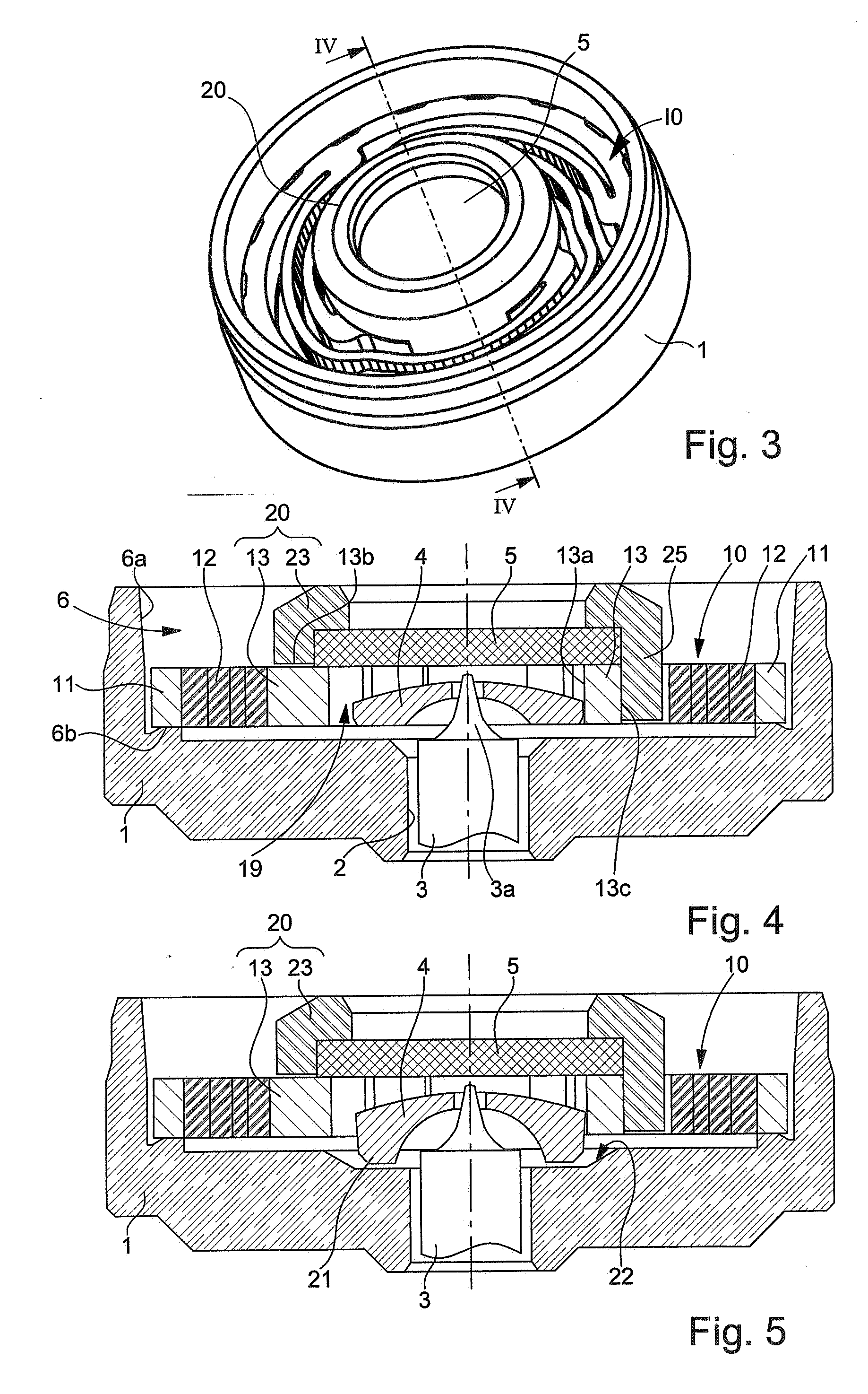
[0023] Referring essentially to FIGS. 3 and 4, a shock absorber bearing according to the invention, for preventing the pivot-shank of a timepiece balance-staff from breaking or being moved off-centre, will be described hereinafter. Those construction elements that are identical or similar to those of the prior art illustrated in the preamble by FIGS. 1 and 2 will be designated by the same references.

[0024] The bearing includes a support block 1 of circular shape delimiting a recess 6 whose centre is pierced with a hole 2 to allowing passage of a balance-staff 3 ending in a pivot-shank 3a.

[0025] The support block 1 can be either an independent piece driven or fixed by any other means in the frame of the watch movement, or it can form part of another piece of the movement, such as a bridge or plate.

[0026] As can be seen, selling 20 which carries the pierced stone 4 through which pivot-shank 3a passes, and endstone 5, is in a way, suspended in recess 6 by spring 10. Spring 10, shown...


PUM


Abstract

The housing (6) of the bearing block (1), locks the peripheral ring (11) of a spring (10) with axial and radial deformation further comprising a substantially annular rigid central support (13) which cooperates with a cap (23), fitted by means of lugs (25) to the outside of the central support (13), to hold the pierced stone (4) and the endstone (5). The resilient part (12) of the spring (10) is for example formed of bent arms.

Description

[0001] This application claims priority from European Patent Application No. 05003868.6 filed Feb. 23, 2005, the entire disclosure of which is incorporated herein by reference FIELD OF THE INVENTION [0002] The present invention concerns a shock absorber bearing for a timepiece, and more particularly, the balance staff bearing of a mechanical watch, for preventing the pivot of small diameter, located at its end and designated the “pivot-shank” from breaking, in the event of an axial or lateral shock, that could simply result from an abrupt movement of the user's wrist. BACKGROUND OF THE INVENTION [0003] Mechanical watch designers have for a long time devised numerous devices for absorbing the energy resulting from a shock, particularly a lateral shock, by the balance staff abutting against a wall of the hole in the base block through which it passes, while allowing a momentary movement of the pivot-shank before it is returned to its rest position via the action of a spring. [0004]FIG...

Claims


Application Information

Patent Timeline
IPC IPC(8): G04B29/00
CPCG04B31/04
Inventor CONUS, THIERRYHELFER, JEAN-LUC
Owner ETA SA MFG HORLOGERE SUISSE
Why Eureka
Try Eureka