Diffraction optical element
A technology of diffractive optical elements and diffraction gratings, applied in optical elements, diffraction gratings, optics, etc., can solve problems such as uneven hue, cracks in the optical adjustment layer, and difficulty in obtaining optical performance diffractive optical elements, etc., to reduce uneven hue , wide manufacturing tolerance, increase the effect of offset tolerance
- Summary
- Abstract
- Description
- Claims
- Application Information
AI Technical Summary
Problems solved by technology
Method used
Image
Examples
no. 1 Embodiment approach
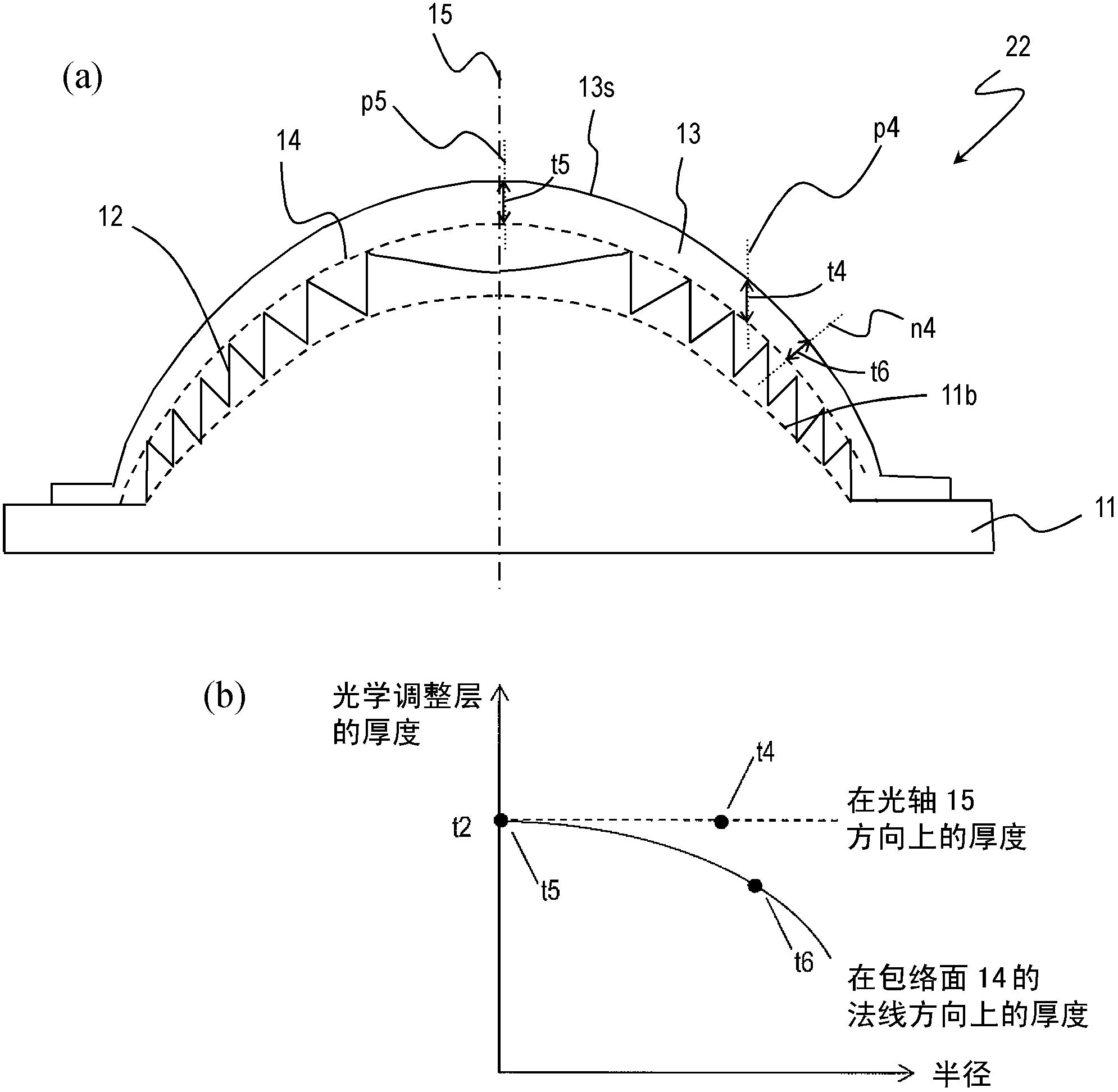
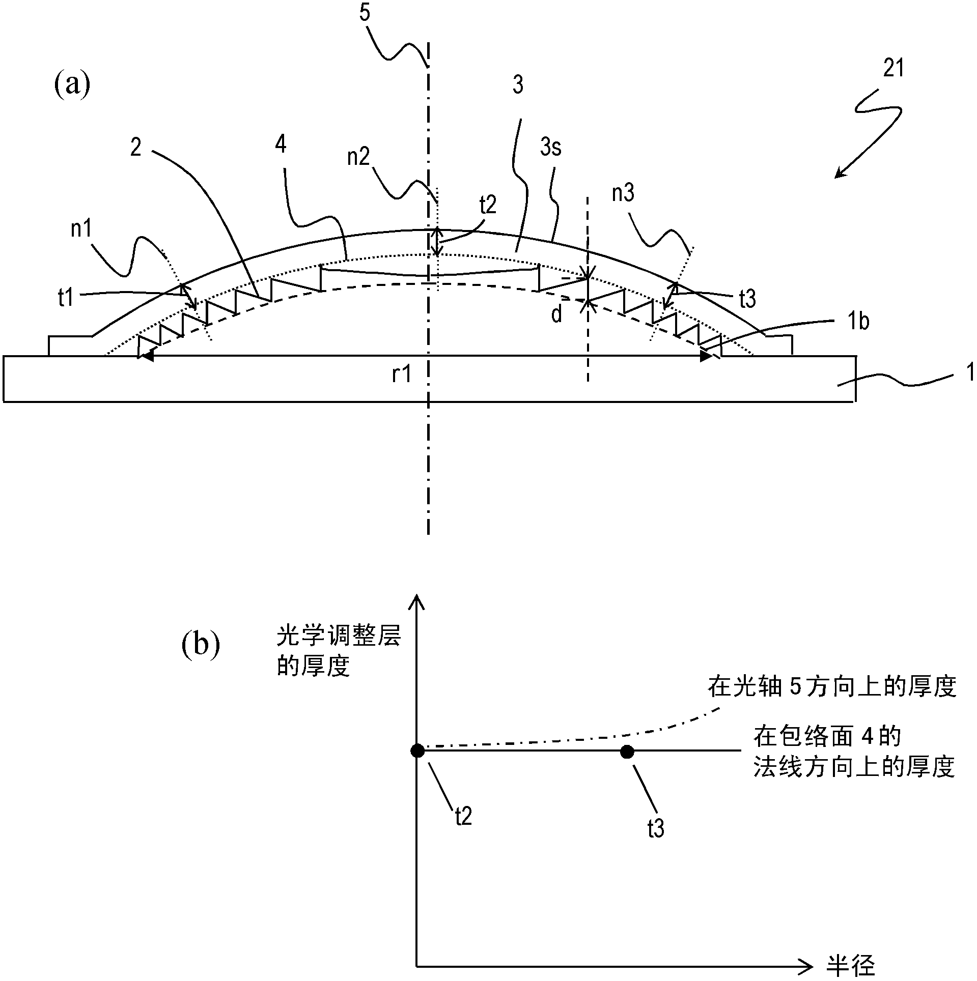
[0051] figure 2 (a) is a sectional view showing an embodiment of the diffractive optical element of the present invention. The diffractive optical element 21 includes a base 1 and an optical adjustment layer 3 . The substrate 1 is made of a first optical material, and the optical adjustment layer 3 is made of a second optical material including a second resin.
[0052] A diffraction grating 2 is provided on one main surface of the substrate 1 . The cross-sectional shape, arrangement, pitch, and depth of the diffraction grating 2 are determined according to the optical properties of the substrate 1 and the optical adjustment layer 3 , and the optical design of the final diffractive optical element 21 to be obtained. For example, to make the diffraction grating 2 function as a lens, it is only necessary to arrange the rings having a zigzag cross-sectional shape in concentric circles so that the pitch gradually decreases from the center to the periphery of the lens. In this c...
no. 2 Embodiment approach
[0082] A second embodiment of the diffractive optical element of the present invention will be described. Figure 4 A cross section of the diffractive optical element 121 is schematically shown. The diffractive optical element 121 differs from the first embodiment in that a synthetic material in which inorganic particles 6 are dispersed in a second resin 7 is used as the second optical material constituting the optical adjustment layer 3'. The applicant of the present invention proposed a diffractive optical element using such a composite material for an optical adjustment layer in International Publication No. 07 / 026597.
[0083] The refractive index and Abbe's number of the second optical material can be adjusted by using a synthetic material in which the inorganic particles 6 are dispersed in the second resin 7 . Therefore, the diffraction efficiency in the wavelength band of the diffractive optical element 121 can be improved by applying the adjusted second optical materi...
Embodiment 1
[0104] Produced with figure 2 (a) Diffractive optical element with the structure shown. The diffractive optical element 21 functions as a lens and is designed to utilize first-order diffracted light. This also applies to the following examples.
[0105] First, polycarbonate resin (d-line refractive index 1.585, Abbe number 28) is injection-molded as the first resin constituting the first optical material of the base body 1, and the envelope surface 4 at the front end of the diffraction grating 2 is produced as A base 1 having an aspheric shape and a ring-shaped diffraction grating 2 having a depth of 39 μm is provided on one surface. The effective radius of the lens part is 1.445 mm, the number of tires is 24, the minimum tire pitch is 30 μm, and the paraxial R [radius of curvature] of the diffractive surface is -1.0144 mm. In addition, the focal length of the diffractive optical element is 1.109mm.
[0106] Next, as a raw material for the second resin of the optical adju...
PUM
 Abstract
Description
Claims
Application Information
 - R&D
- Intellectual Property
- Life Sciences
- Materials
- Tech Scout
- Unparalleled Data Quality
- Higher Quality Content
- 60% Fewer Hallucinations
Browse by: Latest US Patents, China's latest patents, Technical Efficacy Thesaurus, Application Domain, Technology Topic, Popular Technical Reports.
© 2025 PatSnap. All rights reserved.Legal|Privacy policy|Modern Slavery Act Transparency Statement|Sitemap|About US| Contact US: help@patsnap.com


