Superconductive filter with capacitive patches providing reduced cross-coupling

a superconductive filter and capacitive patch technology, applied in the field of planar circuits, can solve the problems of significant coupling stray between non-adjacent parts of the circuit, the size of individual filter elements in the hts microstrip filter, and the limitations of the available size of suitable substrates and deposition equipment, so as to achieve a wide range of manufacturing tolerances and more layout flexibility

Inactive Publication Date: 2008-10-14
SUPERCONDUCTOR TECHNOLOGIES INC
View PDF21 Cites 10 Cited by
  • Summary
  • Abstract
  • Description
  • Claims
  • Application Information

AI Technical Summary

Benefits of technology

[0009]The invention provides filters of planar circuit type such as microstrip and stripline circuits utilizing the resonators that are more compact, allow broader manufacturing tolerances, and allow for more layout flexibility than is attainable with the technology of the prior art.

Problems solved by technology

The size of individual filter elements in HTS microstrip filters is limited not only by the requirements of the base station, but also by limitations in the available sizes of suitable substrates and deposition equipment.
The large end patches also introduce significant stray couplings between non-adjacent parts of the circuit.
The effect of stray couplings can significantly distort the filter response, which makes precise control of the couplings quite difficult.
In addition, the size of the filter can be undesirably large due to the large gap size required.

Method used


Image

  • Superconductive filter with capacitive patches providing reduced cross-coupling
  • Superconductive filter with capacitive patches providing reduced cross-coupling
  • Superconductive filter with capacitive patches providing reduced cross-coupling

Examples


Embodiment Construction

[0028]Illustrative embodiments of the invention are described below. In the interest of clarity, not all features of an actual implementation are described in this specification. It will of course be appreciated that in the development of any such actual embodiment, numerous implementation-specific decisions must be made to achieve the developers' specific goals, such as compliance with system-related and business-related constraints, which will vary from one implementation to another. Moreover, it will be appreciated that such a development effort might be complex and time-consuming, but would nonetheless be a routine undertaking for those of ordinary skill in the art having the benefit of this disclosure.

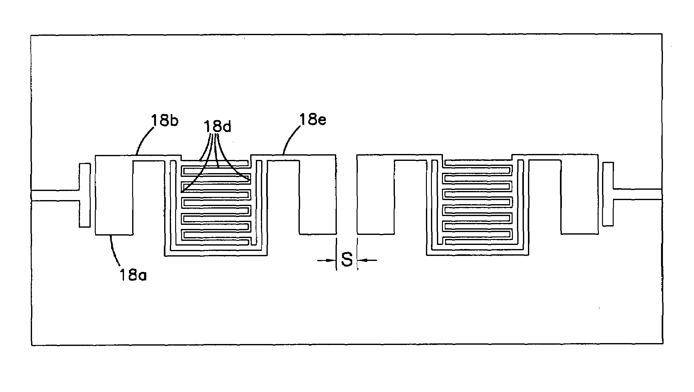
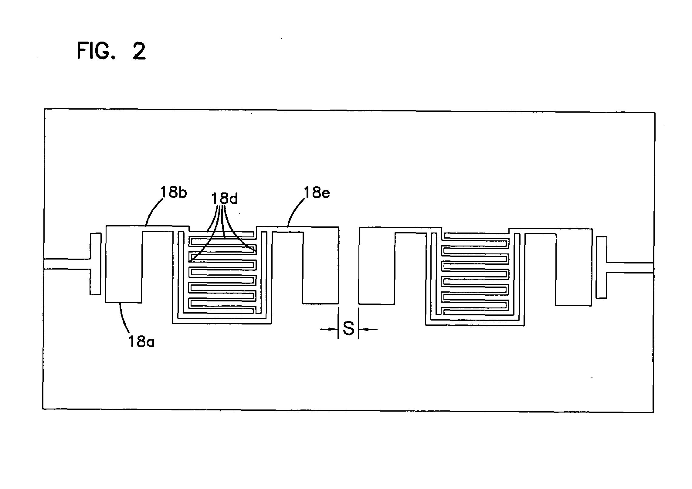
[0029]Referring to FIG. 3, which shows a microstrip filter according to one aspect of the invention, resonators 32 and 34 are placed side-by-side and between the input and output coupling structures 30 and 36. The four structures 30, 32, 34 and 36 are made of conductive materials ...


PUM

PropertyMeasurementUnit
widthaaaaaaaaaa
sizeaaaaaaaaaa
conductiveaaaaaaaaaa

Abstract

A resonator of a planar circuit type is provided for receiving a signal from an input end and transmitting a signal to an output end. The resonator includes: (a) a dielectric substrate; (b) a ground plane including a layer of conductive material formed on the bottom surface of the substrate; (c) an inductor formed on the top surface of the substrate and connected to the input and output ends; and (d) a series capacitor connected in parallel to the inductor, wherein the series capacitor includes two patches of conductive material formed on the top surface of the substrate, each patch being connected to one respective end of the resonator. Each patch also forms a shunt capacitor with the ground plane, and the capacitance of the shunt capacitor constitutes the majority of capacitance between the ground plane and the end of the resonator that is connected to the patch. The conductive material may be a superconductor, including oxide superconductors. Filters utilizing multiple resonators of the invention are also described. The integration of the series and shunt capacitors results in a more compact resonator and filter layout, allows broader manufacturing tolerances, and allows for more layout flexibility than is attainable with the technology of the prior art.

Description

BACKGROUND OF THE INVENTION[0001]1. Field of the Invention[0002]The present invention relates generally to planar circuits, more particularly to microstrip filters, and still more particularly to a microstrip resonator having a capacitor-loaded inductor wherein a capacitive element connected in parallel with an inductor is also the primary shunt capacitor of the resonator.[0003]2. Description of the Related Art[0004]Bandpass filters have wide applications in the today's communication systems. The escalating demand for communication channels dictates better use of frequency bandwidth. This demand results in increasingly more stringent requirements for RF filters used in the communication systems. Some applications require very narrow-band filters (as narrow as 0.05% bandwidth) with high signal throughput within the bandwidth. The filter shape must have sharp skirts so that a maximum amount of the available bandwidth may be utilized. Further, there is an increasing demand for small ba...

Claims


Application Information

Patent Timeline
Patent Type & Authority Patents(United States)
IPC IPC(8): H01P1/203H01B12/02H01P7/08
CPCH01P1/20336H01P1/20381H01P7/082H01P7/084
Inventor YE, SHENLIANG, JI-FUH
Owner SUPERCONDUCTOR TECHNOLOGIES INC
Why Eureka
Try Eureka