Method for fastening a conduit on a support by means of freely adjustable captive flanges

a captive flange, freely adjustable technology, applied in the direction of machines/engines, combustion air/fuel air treatment, charge feed systems, etc., can solve the problems of inability to adjust the relative position of the flange, the manufacturing of such flanges constituted of several components, and the inability to manufacture such flanges of at least one body made of a more rigid material, etc., to achieve simple, rapid and cost-effective implementation, wide variety of manufacturing tolerances

Inactive Publication Date: 2019-04-16
AKWEL VANNES FRANCE
View PDF7 Cites 0 Cited by
  • Summary
  • Abstract
  • Description
  • Claims
  • Application Information

AI Technical Summary

Benefits of technology

[0011]Consequently, the objects assigned to the invention aim to overcome the aforementioned drawbacks and to propose a new method of fastening a mechanical part on a support which is capable of being adapted to a wide variety of fastening conditions, and in particular which allows compensating a wide variety of manufacturing tolerances, while being particularly simple, rapid and cost-effective to implement.
[0014]providing on the first segment at least one stop, and on the fastening flange at least one bearing member, designed to cooperate with the stop so as to limit, in a loose configuration, the stroke of the fastening flange relative to the first segment, in the at least one degree of freedom, to a predetermined allowed displacement range which allows freely selecting a position of the flange relative to the first segment, called <<adapted position>> among a plurality of accessible positions,
[0018]Advantageously, the invention allows pre-constituting a complete subassembly which comprises the mechanical part (the conduit) and the number of fastening flanges necessary for the fastening of said part, pre-positioned in the vicinity of their adapted position, so that it is no longer necessary to provide additional flanges in order to mount said subassembly on the support.
[0019]The subassembly may therefore be easily prepared separately from the support, on a first assembly line, before being transported to a second assembly line distant from the first one, in order to be assembled there on the support.
[0021]Advantageously, pre-positioning and maintaining the flanges in the respective displacement ranges thereof, thanks to the stop and bearing member system specific to the invention, facilitates the subsequent mounting of the sub-assembly on the support, since the flanges are already in the immediate vicinity of their final position (adapted position), while nevertheless preserving the necessary and sufficient displacement capacity, within their displacement range, in order to accommodate, in rotation and / or in translation, the variations in the assembly configuration which are induced by the manufacturing tolerances of the support and / or the subassembly.
[0024]Thanks to the invention, the mere fact of positioning the subassembly relative to the support, and more particularly of placing the lugs in contact with the support, as long as the flange is in a loose configuration, causes the flange to be positioned and oriented spontaneously in an adapted position, which compensates the possible manufacturing tolerances.

Problems solved by technology

The drawback of such an arrangement is that the lugs are rigidly connected to the conduit, and therefore may not be adjusted as a function of the manufacturing and assembly tolerances.
However, one drawback of such an arrangement lies in the fact that, in order to prevent the flange from being lost by sliding and falling from the conduit, the body of the flange and the elastomer pad must be dimensioned so that the elastomer pad exerts a tightening on the conduit as soon as the flange is placed on said conduit.
In practice, here again, and because of the high friction that the elastomer exerts against the conduit, it is not possible to adjust the position of the flange relative to the conduit, after having placed the flange on the conduit, without to risking to damage, and in particular to rip off or tear, the elastomer pad, or even to damage the conduit.
Furthermore, the manufacture of such flanges constituted of several components, which comprise at least one elastomer pad carried by at least one body made of a more rigid, generally metal, material, may be relatively complex and expensive.

Method used


Image

  • Method for fastening a conduit on a support by means of freely adjustable captive flanges
  • Method for fastening a conduit on a support by means of freely adjustable captive flanges
  • Method for fastening a conduit on a support by means of freely adjustable captive flanges

Examples


Embodiment Construction

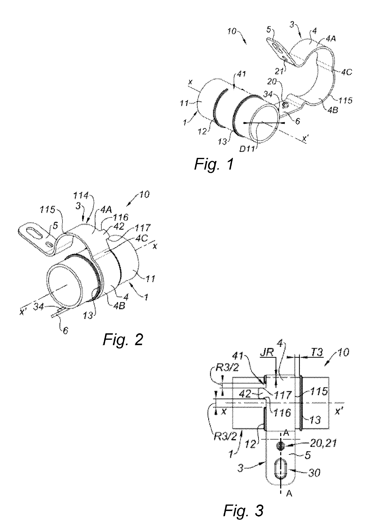
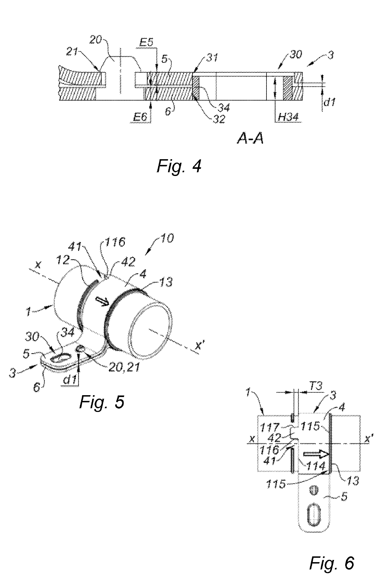
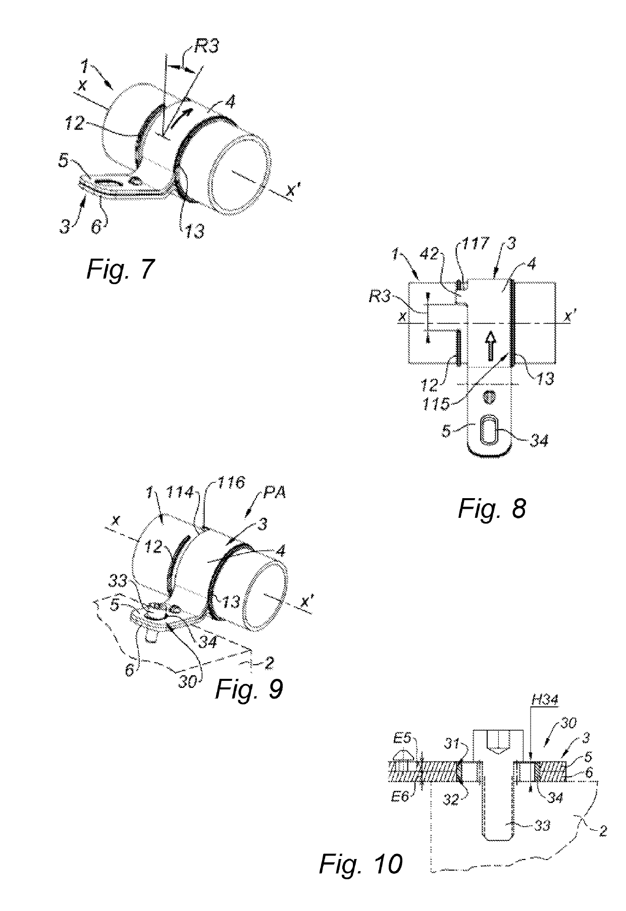
[0035]The present invention concerns a fastening method configured to fasten a mechanical part 1, such as a conduit 1, on a support 2, such as a vehicle engine or chassis, by means of a fastening flange 3, as illustrated in FIG. 9.

[0036]In the following, and for convenience of description, the mechanical part 1 might be assimilated to a conduit, configured to convey any fluid, and more particularly to a conduit configured to convey a fluid called automotive fluid such as, for example, a fuel, air, in particular intake air configured to form an oxidizer within a combustion engine, a gas, a mixture of gas or of liquid and gas, in particular exhaust gases, vapor, in particular an oil vapor, a brake liquid, a coolant, an urea solution for the catalytic depollution of the exhaust gases, a washing solution for windshield washer, etc.

[0037]Said part 1 is preferably made of a polymer material, preferably rigid, and for example made of a thermoplastic polymer such as: polyamide (PA), polybut...


PUM


Abstract

A fastening method configured to fasten a mechanical part on a support by means of a fastening flange, the method including: placing the fastening flange on a first segment of the part, in a loose configuration, providing on the first segment at least one stop and on the fastening flange at least one bearing member, which cooperates with the stop so as to limit, in the loose configuration, the stroke of the fastening flange to a predetermined allowed displacement range, which allows to freely select an adapted position among a plurality of accessible positions, and to provide on the flange a locking mechanism arranged such that, when the subassembly is fastened to the support by means of the at least one lug, then a locking of the body of the fastening flange is automatically caused on the mechanical part in the adapted position.

Description

TECHNICAL FIELD OF THE INVENTION[0001]The present invention concerns the fastening of a mechanical member, such as a conduit used for a fluid transfer, on a support, such as a vehicle engine or chassis.STATE OF THE ART[0002]It is known to fasten conduits on engine or chassis elements by means of lugs, which support the conduit and which are fastened by screwing on the engine or the chassis.[0003]According to a known arrangement, the lugs may be formed of rigid plastic, and for example molded in one piece with the conduit, overmolded on said conduit, or fastened on the conduit by welding.[0004]The drawback of such an arrangement is that the lugs are rigidly connected to the conduit, and therefore may not be adjusted as a function of the manufacturing and assembly tolerances. Furthermore, such a rigid junction facilitates the transmission of the vibrations.[0005]Another known arrangement consists in providing a flange, distinct from the conduit, and which comprises, on the one hand, a...

Claims


Application Information

Patent Timeline
Patent Type & Authority Patents(United States)
IPC IPC(8): F16L3/24F16L3/14F16L3/12F16L3/123F02M35/10
CPCF16L3/14F16L3/12F16L3/1236F16L3/123F02M35/10144
Inventor ROBINAULT, MICHELGATEAU, DAVID
Owner AKWEL VANNES FRANCE
Why Eureka
Try Eureka