Electrical shielding member for a network connector

a network connector and shielding member technology, applied in the direction of network connectors, couplings/cases, coupling device connections, etc., can solve the problems of time and cost inefficiency in assembling multi-part housings, large and bulky connectors, damage to multi-part housings, etc., to improve electrical shielding, prevent damage due to incorrect assembly, and improve the effect of shielding

Active Publication Date: 2019-10-31
APTIV TECH LTD
View PDF2 Cites 2 Cited by
  • Summary
  • Abstract
  • Description
  • Claims
  • Application Information

AI Technical Summary

Benefits of technology

[0032]Arranging the electrical shielding member within the collector housing so as to be in contact with a shielding of the connector module and a shielding of a corresponding connector module allows for a continuous inline shielding of the electrical signal lines of the respective connector modules, not only in the mating region. Thus, a significant improvement of the shielding can be achieved.
[0033]Still further, the collector housing may comprise a corresponding coupling element that couples with the coupling element of the electrical shielding member and secures the electrical shielding member in a predefined orientation. The coupling element allows for a correct assembly of the electrical connector assembly, as the electrical shielding member can be inserted in the collector housing only under one predefined orientation. Thus, damages due to incorrect assembly can be prevented.
[0034]Further, the collector housing may be a one-piece collector housing. A one-piece collector housing may be an injection molded plastic part, a 3D printed part, an extruded part or any other part, being provided with suitable manufacturing techniques. In particular, the one-piece collector housing may comprise a plastic material or a compound plastic material. Providing a one-piece collector housing allows for a compact design and therefore for an overall compact size of the electrical connector assembly.
[0035]The electrical shielding member may be arranged within the collector housing so that it surrounds a mating region of the connector module and a corresponding connector module on at least four sides, when the electrical connector assembly is mated with a second electrical connector assembly. Providing a four-side shield allows for a significantly improved electrical shielding, as described above and therefore for increased data rates.

Problems solved by technology

However, known shielding members lead to large and bulky connectors.
This is undesirable as the installation space is limited, especially in vehicles.
These multi-part housings are prone to damages as single parts can get lost, if not assembled correctly.
Further, assembling multi-part housings is time and cost inefficient.

Method used


Image

  • Electrical shielding member for a network connector
  • Electrical shielding member for a network connector
  • Electrical shielding member for a network connector

Examples


Embodiment Construction

[0055]Reference will now be made in detail to embodiments, examples of which are illustrated in the accompanying drawings. In the following detailed description, numerous specific details are set forth in order to provide a thorough understanding of the various described embodiments. However, it will be apparent to one of ordinary skill in the art that the various described embodiments may be practiced without these specific details. In other instances, well-known methods, procedures, components, circuits, and networks have not been described in detail so as not to unnecessarily obscure aspects of the embodiments.

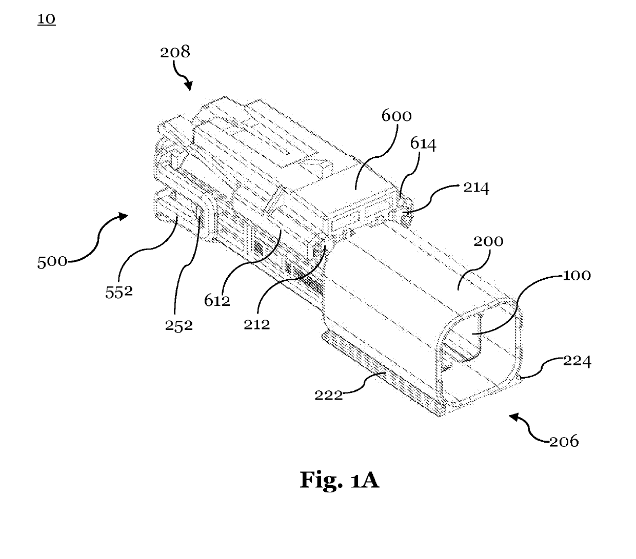
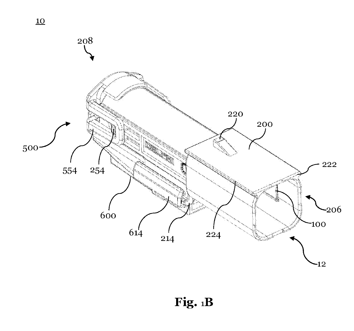
[0056]FIG. 1A shows a schematic top view of an electrical connector assembly 10 and FIG. 1B shows a schematic bottom view of the electrical connector assembly 10 of FIG. 1A. The electrical connector assembly 10 is a male electrical connector assembly that may comprise electrical signal contacts in form of electrical signal pins (not shown). The electrical connector assembly...


PUM


Abstract

The present invention relates to an electrical shielding member for an electrical connector assembly. The electrical shielding member is made from bend and cut sheet metal. The electrical shielding member is configured to be received at least partially within a collector housing of an electrical connector assembly. The electrical shielding member comprises a receiving portion that is configured to receive a connector module and a corresponding connector module at least partially, so as to surround a mating region of the connector module and corresponding connector module on at least four sides.

Description

CROSS-REFERENCE TO RELATED APPLICATION[0001]This application claims the benefit under 35 U.S.C. § 119(e) of U.S. Provisional Patent Application No. 62 / 662,420 filed on Apr. 25, 2018 and further claims the benefit under 35 U.S.C. § 119(a) of Patent Application No. 18170752.2 filed in the European Patent Office on May 4, 2018, the entire disclosure of each of which is hereby incorporated by reference.TECHNICAL FIELD OF THE INVENTION[0002]The present invention relates to an electrical shielding member for an electrical connector assembly, an electrical connector assembly, and an electrical connector system as well as to a method to assemble the electrical connector assembly.BACKGROUND OF THE INVENTION[0003]In recent years, vehicles have been equipped with numerous on-board electronics. These on-board electronics provide a wide field of functionality, such as sensors, control functions and the like. These on-board electronics provide typical consumer electronic functions, navigation con...

Claims


Application Information

Patent Timeline
Patent Type & Authority Applications(United States)
IPC IPC(8): H01R13/6583H01R12/70H01R13/629
CPCH01R2201/26H01R12/7005H01R13/629H01R13/6583H01R13/6581H01R43/20H01R13/50H01R13/6592H01R24/20H01R24/28H01R2201/04
Inventor DROESBEKE, GERTANTIL, MATTHEWVOLKOV, VALERYENSLEY, CORY R.
Owner APTIV TECH LTD
Why Eureka
Try Eureka