Method of operating a flying shear

a flying shear and blade technology, applied in box making operations, paper/cardboard containers, manufacturing tools, etc., can solve the problems of blade increase manufacturing costs, undesirably high, etc., to achieve a wide range of manufacturing tolerances, reduce wear and manufacturing costs, and improve cutting efficiency.

Inactive Publication Date: 2007-08-21
SMS DEMAG AG
View PDF23 Cites 4 Cited by
  • Summary
  • Abstract
  • Description
  • Claims
  • Application Information

AI Technical Summary

Benefits of technology

[0008]It is the object of the present invention to provide a method of operating a flying shear in such a way that wear and manufacturing costs are minimized and broader manufacturing tolerances are achieved without impairing the cutting efficiency.
[0010]Accordingly, in the method according to the present invention, only a partial penetration of the blade or a wedge into the rolling strip is effected in order to significantly reduce the cross-section of the strip at the cutting location in a defined manner and to perform the separation then by tensile forces exerted onto the rolling strip, wherein the use of an anvil drum with a correspondingly complex synchronization is eliminated.

Problems solved by technology

However, it was found that for such shearing processes the wear of the blades and of the anvil surfaces, if employed, is undesirably high, and it was found that the manufacture of the shears must be realized within the most narrow tolerances—a factor increasing manufacturing costs—for achieving an exact placing of the blades onto a anvil or for a defined cut with two blades in order to ensure perfect cutting efficiency.
By a later application of tensile force onto the strip, tearing occurs at the scored areas resulting in a separation of the strip.
Moreover, contacting of the strip with the anvil drum can cause damage to the strip.

Method used


Image

  • Method of operating a flying shear
  • Method of operating a flying shear
  • Method of operating a flying shear

Examples


Embodiment Construction

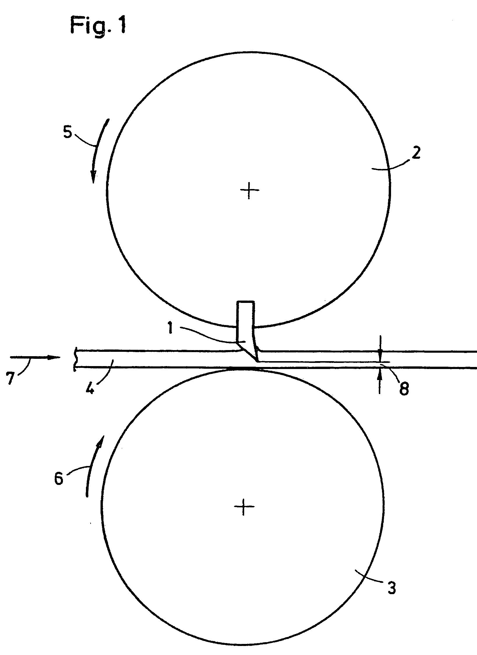
[0017]In FIG. 1, a blade drum 2 supporting a blade 1 is illustrated, and a smooth anvil drum 3 is positioned opposite thereto and acts as the anvil. The rolling strip 4 runs in the direction of arrow 7 between the blade drum rotating in the direction of arrow 5 and the anvil drum 3 rotating in the opposite direction 6.

[0018]Usually, in the case of high-speed shears the blade drum 2 is positioned above the rolling strip 4 to such an extent that its blades 1 do not contact the rolling strip 4. For performing the cut, however, the blade drum 2, driven for several rotations at a peripheral speed matching the feed rate of the rolling strip, is advanced spontaneously by means of an advancing device in the direction toward the anvil drum 3 so that the blade 1 penetrates the rolling strip 4 and cuts it leaving a residual thickness illustrated by the double arrow 8.

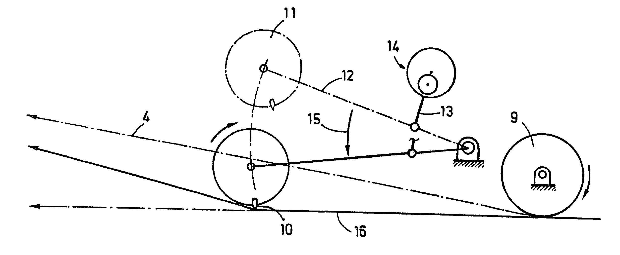
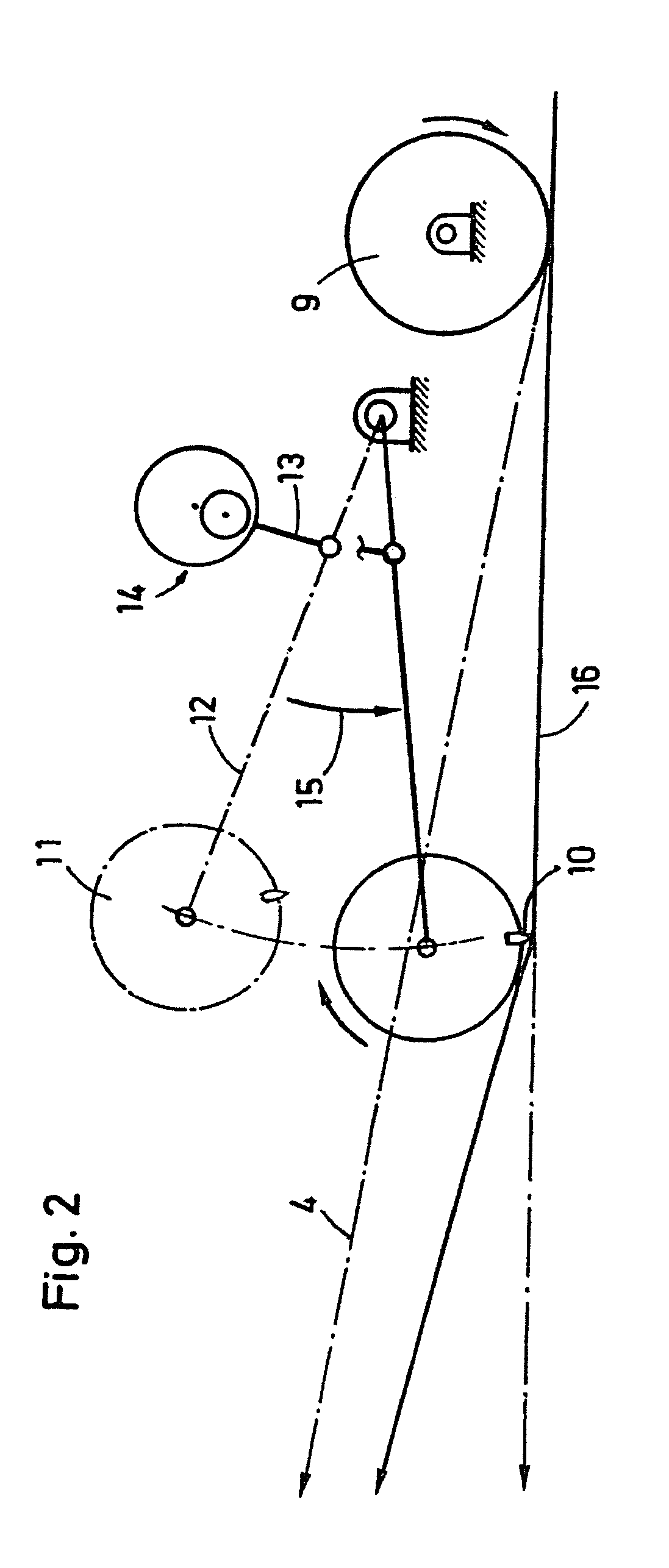
[0019]For a strip which is moved slower, there is the possibility of eliminating the advancing device and, for each movement int...


PUM

PropertyMeasurementUnit
widthaaaaaaaaaa
tensile forceaaaaaaaaaa
massaaaaaaaaaa

Abstract

A method of operating a flying shear for cutting a rolled strip, which includes at least one drum provided with a blade, includes synchronizing a peripheral speed of the blade with a feed rate of the rolled strip, and cutting the rolled strip by effecting a partial penetration of the blade in the rolled strip to produce a weakened location of the rolled strip, and by tearing the rolled strip at the weakened location by a tensile force.

Description

REFERENCE TO RELATED APPLICATIONS[0001]This application is a divisional application of U.S. patent application Ser. No. 09 / 958,621 filed Jan. 3, 2002 now abandoned, which is the national phase of International application PCT / EP00 / 03168, filed Apr. 10, 2000.BACKGROUND OF THE INVENTION[0002]1. Field of the Invention[0003]The present invention relates to a method of operating a flying shear which has at least one drum provided with a blade. The method comprises synchronizing the peripheral speed of the blade with the feed rate of rolled strip.[0004]2. Description of the Related Art[0005]Such synchronized shears are known, for example, from DE 196 37 862 A1 as high-speed shears for cutting rolling strip to length. In this connection, two oppositely positioned drums which can be advanced toward one another are used which are both provided with blades, or only one of the drums is provided with an anvil or is used as an anvil.[0006]The advancing strokes are dimensioned such that the two b...

Claims


Application Information

Patent Timeline
Patent Type & Authority Patents(United States)
IPC IPC(8): B26F3/02B31B1/25B26D1/56B23D25/06B23D25/12B23D31/00B31B50/25B65D90/14B65G69/00
CPCB23D25/12B23D31/002B65D90/14B65G69/003Y10T83/04Y10T83/4676Y10T83/0341Y10T225/12Y10T225/30Y10T83/0515B23D31/00
Inventor GRAFE, HORSTMERZ, JURGENMUNKER, JOCHENNIELSEN, DUANE A.BARRY, MICHAEL L.
Owner SMS DEMAG AG
Why Eureka
Try Eureka