Pump with integrated heating element

a heating element and pump technology, applied in the field of pumps, can solve the problems of increased limescale precipitation, unsatisfactory heating effect, and inability to provide heat output,

Active Publication Date: 2015-03-26
E G O ELEKTRO GERAETEBAU GMBH
View PDF0 Cites 11 Cited by
  • Summary
  • Abstract
  • Description
  • Claims
  • Application Information

AI Technical Summary

Benefits of technology

[0018]It can therefore be achieved by way of the invention as a heating method that, in the method which was mentioned at the outset, the pump chamber wall can be heated by way of a plurality of distributed heating elements which advantageously cover substantially the entire pump chamber wall, even if they do not cover every region directly. The pump chamber wall is heated to a more pronounced effect in the region of a pump bottom under the impeller, in particular at the impeller outlet, than in the region of an outlet from the pump chamber wall, which outlet is arranged in the axial direction away from the pump bottom. In particular, the outlet is arranged as far as possible away from the pump bottom, that is to say, as it were, at the other end of the pump chamber or the pump chamber wall.

Problems solved by technology

Such a large quantity of heating power output can then no longer be coupled into the water which flows toward the outlet in the axial course and becomes warmer in this direction, and / or there can be the risk of local overheating which can lead to increased precipitation of limescale which is contained or the like in the water and is undesirable on the heating elements or the pump chamber wall itself.
Above all, as a result of reduced overheating of the water, the formation of limescale on the pump chamber wall can be reduced, which is generally disruptive and then in turn impairs the degree of efficiency of the heating.

Method used


Image

  • Pump with integrated heating element
  • Pump with integrated heating element
  • Pump with integrated heating element

Examples


Embodiment Construction

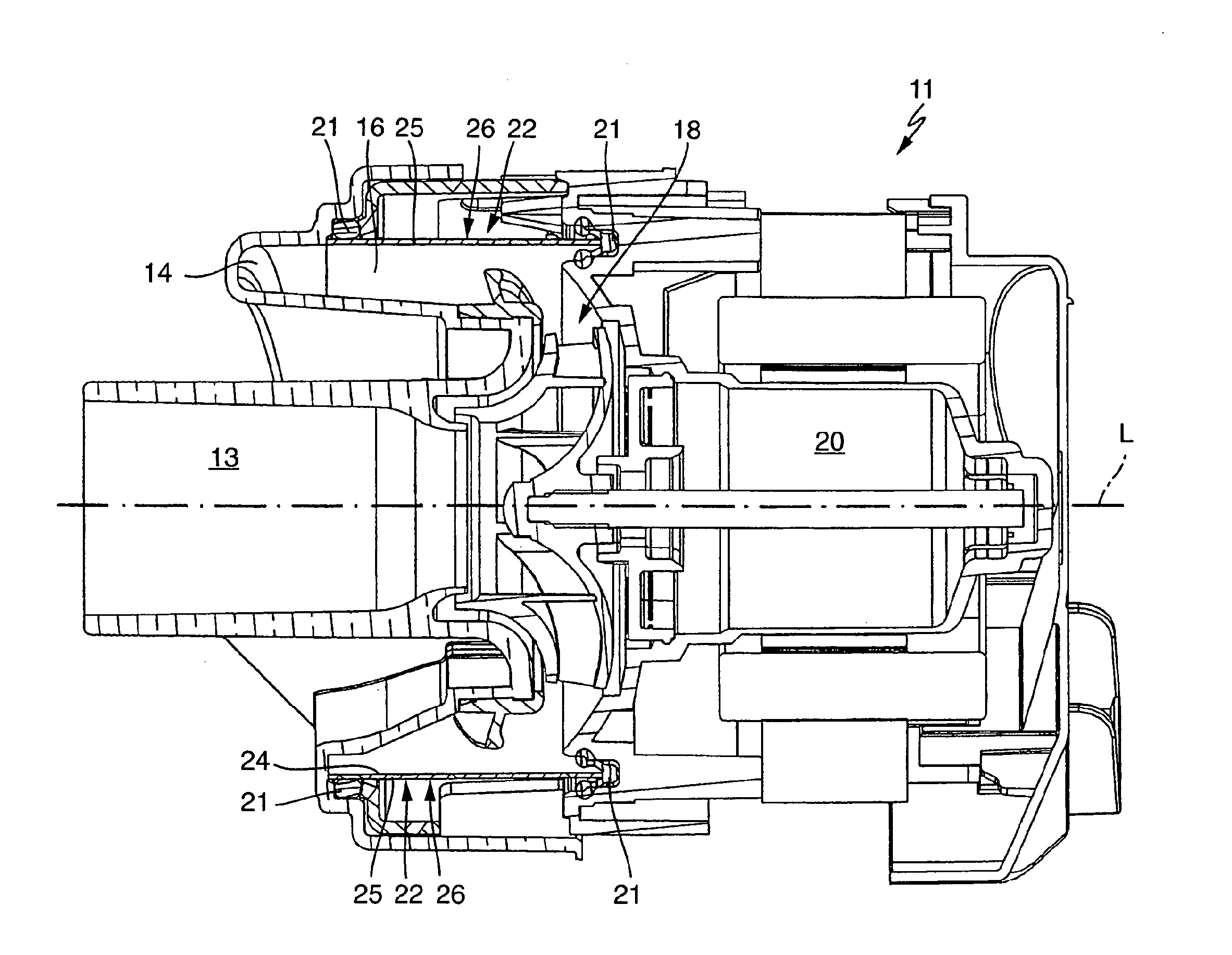
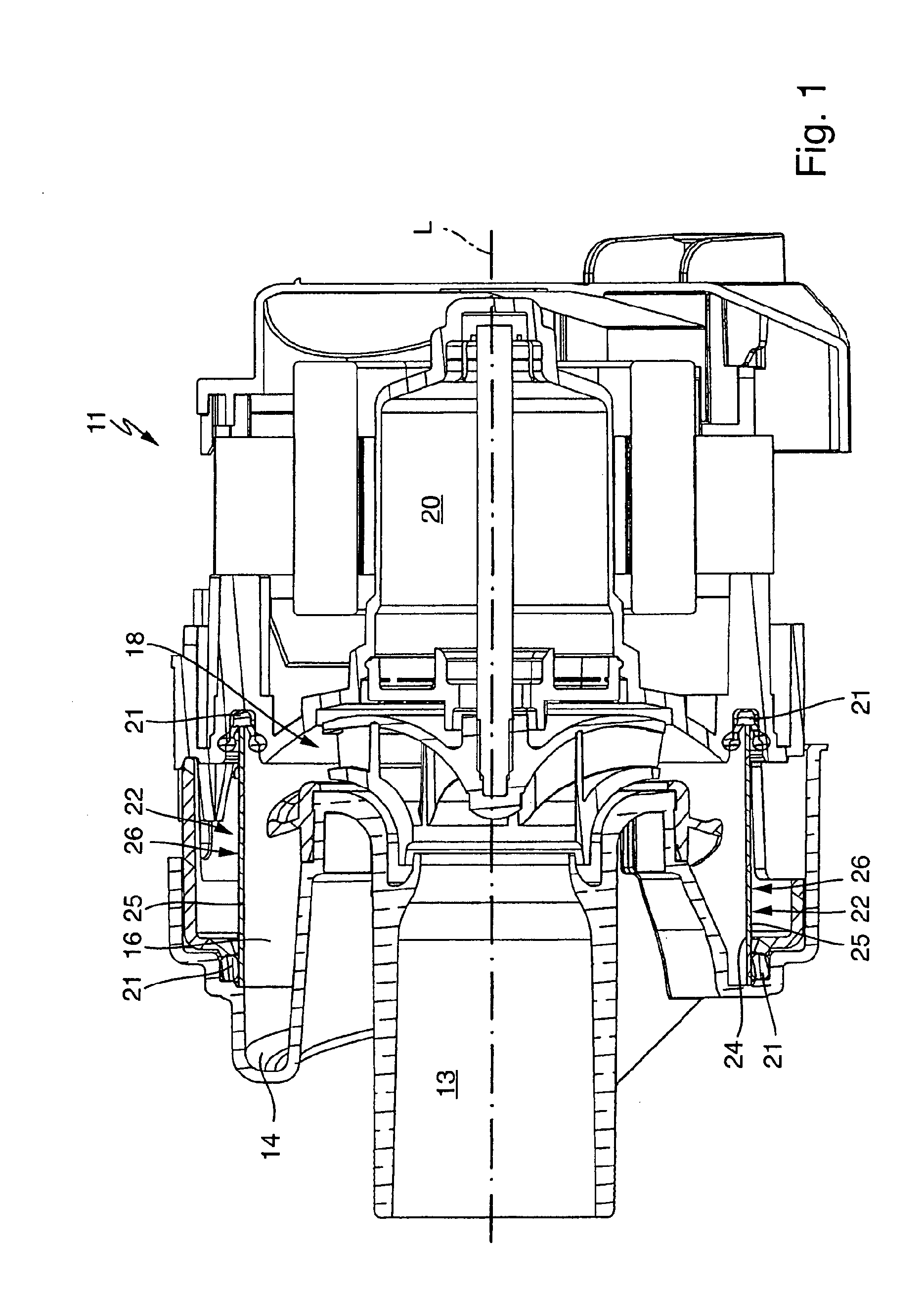
[0024]FIG. 1 shows a pump 11 according to the invention in section, the design of which as a radial pump or impeller pump corresponds substantially to DE 102007017271 A1 mentioned at the outset, to which reference is made in this regard explicitly. It can advantageously be used in a dishwasher or a washing machine. In the left-hand region, the pump 11 has a pump housing 12 with an inlet 13, an outlet 14 and a pump chamber 16. A customary impeller 18 is arranged as rotor or pump impeller close to a pump chamber bottom 17. It is driven by a pump motor 20 which is not described in greater detail. By way of rotation of the impeller 18, fluid is sucked in at the inlet 13 in the axial direction along the longitudinal center axis L (shown using a dashed line) of the pump 11 and is then ejected by the impeller 18 in the radial direction. The fluid is then brought into circulation in the pump chamber 16 and circulates and finally exits from the pump 11 at the outlet 14. To this end, it has a...


PUM


Abstract

A pump for a dishwasher is configured as an impeller pump having a central water inflow to a rotating impeller for conveying the water in the radial direction out of the impeller into a pump chamber which surrounds the impeller in a ring-like manner and has a heated pump chamber wall on its outer side. Here, the pump has an outlet in the end region of the pump chamber at an axial spacing from the impeller. Heating elements which have a decreasing power output with regard to the area power output in the axial direction of the pump toward the outlet are arranged on the pump chamber wall. An input of energy into the pump chamber can thus be varied and in the process adapted depending on a turbulent or laminar flow.

Description

CROSS-REFERENCE TO RELATED APPLICATIONS[0001]This application is a National Stage application, filed under 35 U.S.C. §371, of International Application PCT / EP2013 / 052353, filed Feb. 6, 2013, which claims priority to German Application No. 10 2012 202 065.9 filed Feb. 10, 2012 both of which are hereby incorporated by reference in their entirety.TECHNOLOGICAL FIELD[0002]The invention relates to a pump, as can be used, in particular, for a water-conducting domestic appliance such as a dishwasher or a washing machine. Furthermore, the invention relates to a method for heating a pump, in particular an abovementioned pump according to the invention.[0003]A pump of the generic type is known, for example, from DE 102007017271 A1.BACKGROUND[0004]The invention is based on the problem of providing a pump as mentioned at the outset and a corresponding method for heating a pump, by way of which problems of the prior art can be avoided, in particular with regard to limescale formation on a heated...

Claims


Application Information

Patent Timeline
Patent Type & Authority Applications(United States)
IPC IPC(8): F04D29/58F04D27/00F04D19/00
CPCF04D29/584F04D27/006F04D19/00A47L15/4225A47L15/4285D06F39/04D06F39/085F04D29/426F04D29/586F04D29/588F04D29/5866
Inventor KOEBRICH, HOLGERALBERT, TOBIASBLOCK, VOLKER
Owner E G O ELEKTRO GERAETEBAU GMBH
Why Eureka
Try Eureka