Heat engine with cascaded cycles

a cascaded cycle and heat engine technology, applied in machines/engines, steam engine plants, solar thermal energy generation, etc., can solve the problems of complexity, cost or low efficiency, and the inability of recirculation to produce a useful energy output by the system, and achieve low emissivity, high surface area, and high absorption efficiency

Inactive Publication Date: 2011-11-10
SOLARTREC
View PDF37 Cites 36 Cited by
  • Summary
  • Abstract
  • Description
  • Claims
  • Application Information

AI Technical Summary

Benefits of technology

[0007]In one practical embodiment, a concentrated beam of solar radiation is directed through a high temperature resistant window, for example, of sapphire or any other suitable material, onto a thin film or droplet of water. The thin film or droplet can be sitting on or near a “

Problems solved by technology

Several different types of heat engines have been used in practice to convert concentrated solar radiation to mechanical power, notably Stirling cycle engines and Rankine cycle engines, however, all such known engines have had disadvantages relating to complexity, cost or low efficiency, Apparatus which convert heat energy into mechanical energy, namely the heat energy of concentrated beam of solar radiation into the m

Method used


Image

  • Heat engine with cascaded cycles
  • Heat engine with cascaded cycles
  • Heat engine with cascaded cycles

Examples


Embodiment Construction

[0166]This invention is not limited in its application to the details of construction and the arrangement of components set forth in the following description or illustrated in the drawings. The invention is capable of other embodiments and of being practiced or of being carried out in various ways. Also, the phraseology and terminology used herein is for the purpose of description and should not be regarded as limiting. The use of “including,”“comprising,” or “having,”“containing,”“involving,” and variations thereof herein, is meant to encompass the items listed thereafter and equivalents thereof as well as additional items.

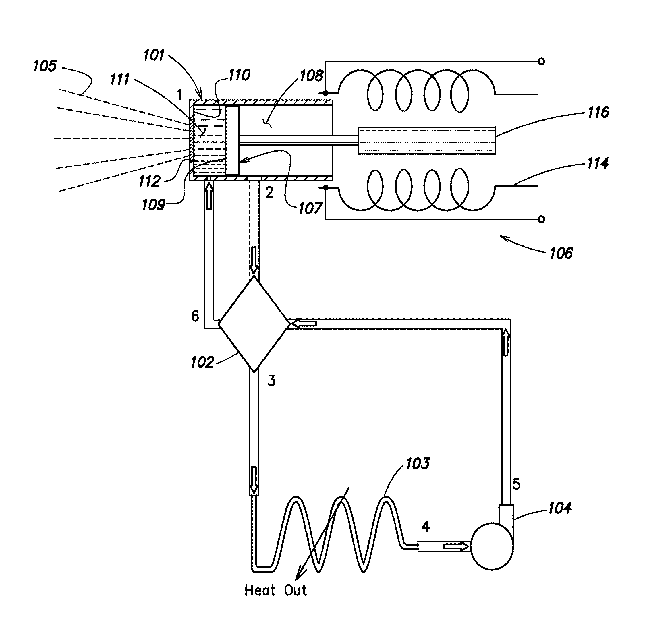
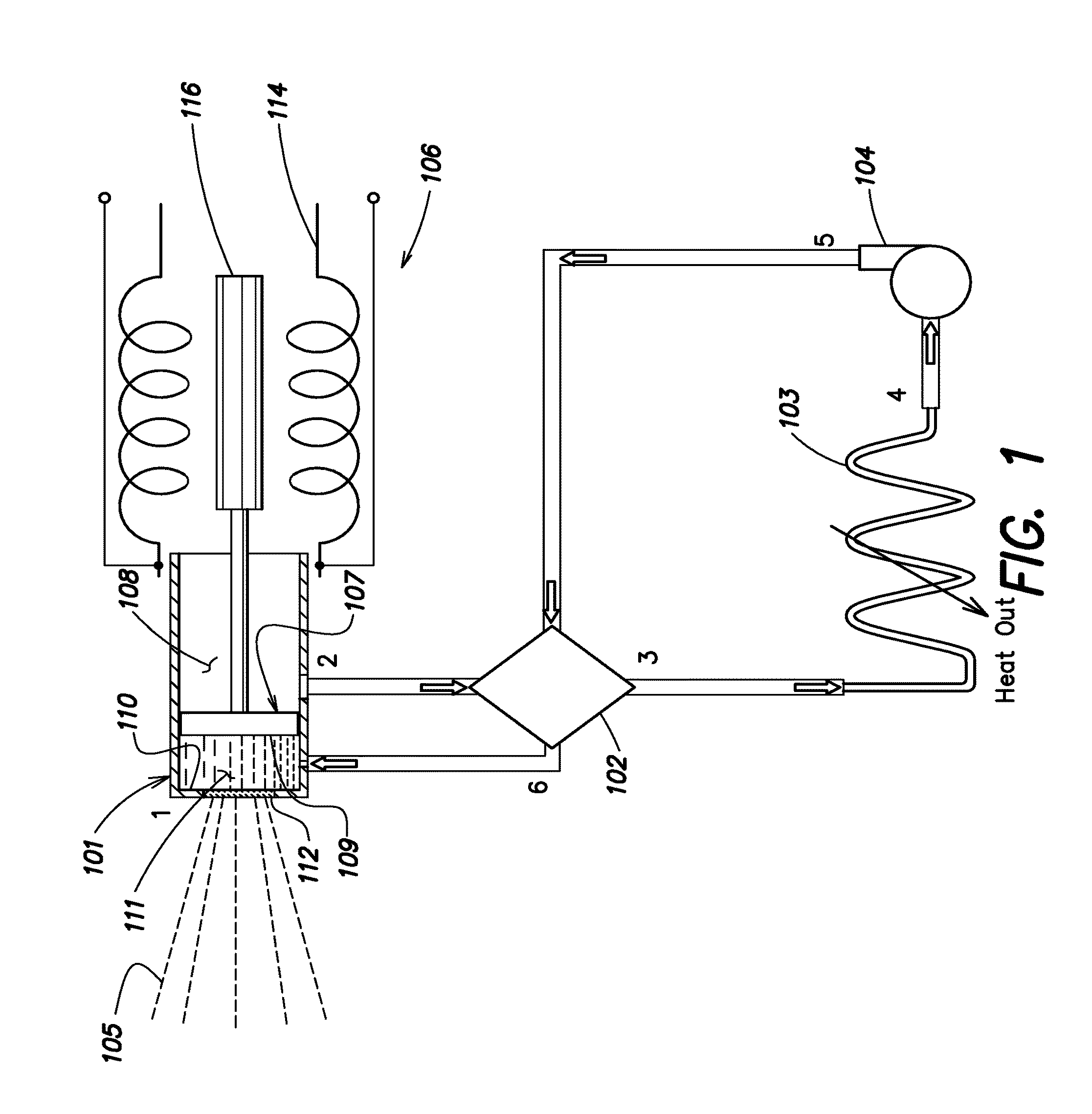
[0167]A single sided expander and its working cycle is now described. The single sided expander includes an oscillating piston and linear electrical generator. The single sided expander is derived from actual experimental rig results. It will be understood that expanders operating on the principles illustrated by the single sided expander but employing more than...


PUM


Abstract

A method of converting thermal energy into another energy form using a thermodynamic cycle is disclosed, the method including the steps of: pressurizing a working fluid; supplying thermal energy to heat the working fluid from a liquid or substantially liquid state to a supercritical fluid state; in a first expander, substantially isentropically expanding the working fluid to yield energy in the other energy form; separating the expanded working fluid to form a first portion of the fluid diverted to a second expander and a second portion of the working fluid diverted to bypass the second expander; in the second expander, substantially isentropically expanding the first portion of the working fluid to yield energy in the other energy form; condensing the expanded first portion of the working fluid to a liquid or substantially liquid state; and recombining the first and second portions of the working fluid to be recirculated in the cycle.

Description

RELATED APPLICATIONS[0001]This application is related to U.S. Provisional Application Ser. No. 60 / 719,327, entitled “PIEZOELECTRIC SELECTABLY ROTATABLE BEARING,” filed on Sep. 21, 2005, Application Ser. No. 60 / 719,328, entitled “SOLAR HEAT ENGINE SYSTEM,” filed on Sep. 21, 2005, U.S. application Ser. No. 11 / 512,568, entitled “SOLAR HEAT ENGINE SYSTEM,” filed on Aug. 30, 2006, and application Ser. No. 12 / 246,127, entitled “HEAT ENGINE IMPROVEMENTS,” filed on Oct. 6, 2008 each of which are herein incorporated by reference in its entirety.BACKGROUND[0002]This disclosure relates to the conversion of heat energy to another form of energy, e.g. mechanical energy. The disclosure further relates to such conversion where the heat energy source is concentrated solar energy or a low grade or waste heat source.[0003]Several different types of heat engines have been used in practice to convert concentrated solar radiation to mechanical power, notably Stirling cycle engines and Rankine cycle engi...

Claims


Application Information

Patent Timeline
IPC IPC(8): F01K13/00F01K21/00F01K25/08
CPCF01K7/32Y02E10/46F01K25/08
Inventor WALPITA, NALINBRISSON, JOHN G.
Owner SOLARTREC
Why Eureka
Try Eureka