
Blackbody cavity for calibration of infrared thermometers

a blackbody cavity and infrared thermometer technology, applied in the field of electromagnetic emission test equipment, can solve the problems of not being able to achieve uniform walls, not being able to consider painted surfaces, and being difficult to ensure uniform walls, etc., to achieve high emissivity, easy to manufacture and maintain, and low emissivity

Inactive Publication Date: 2002-09-10
ADVANCED MONITORS
View PDF14 Cites 39 Cited by
  • Summary
  • Abstract
  • Description
  • Claims
  • Application Information

AI Technical Summary

Benefits of technology

to provide a blackbody cavity having smaller dimensions. And it is a further object to provide a blackbody cavity which is easy to manufacture and maintain. Naturally, not every embodiment of the present invention will achieve all of these objects and advantages.
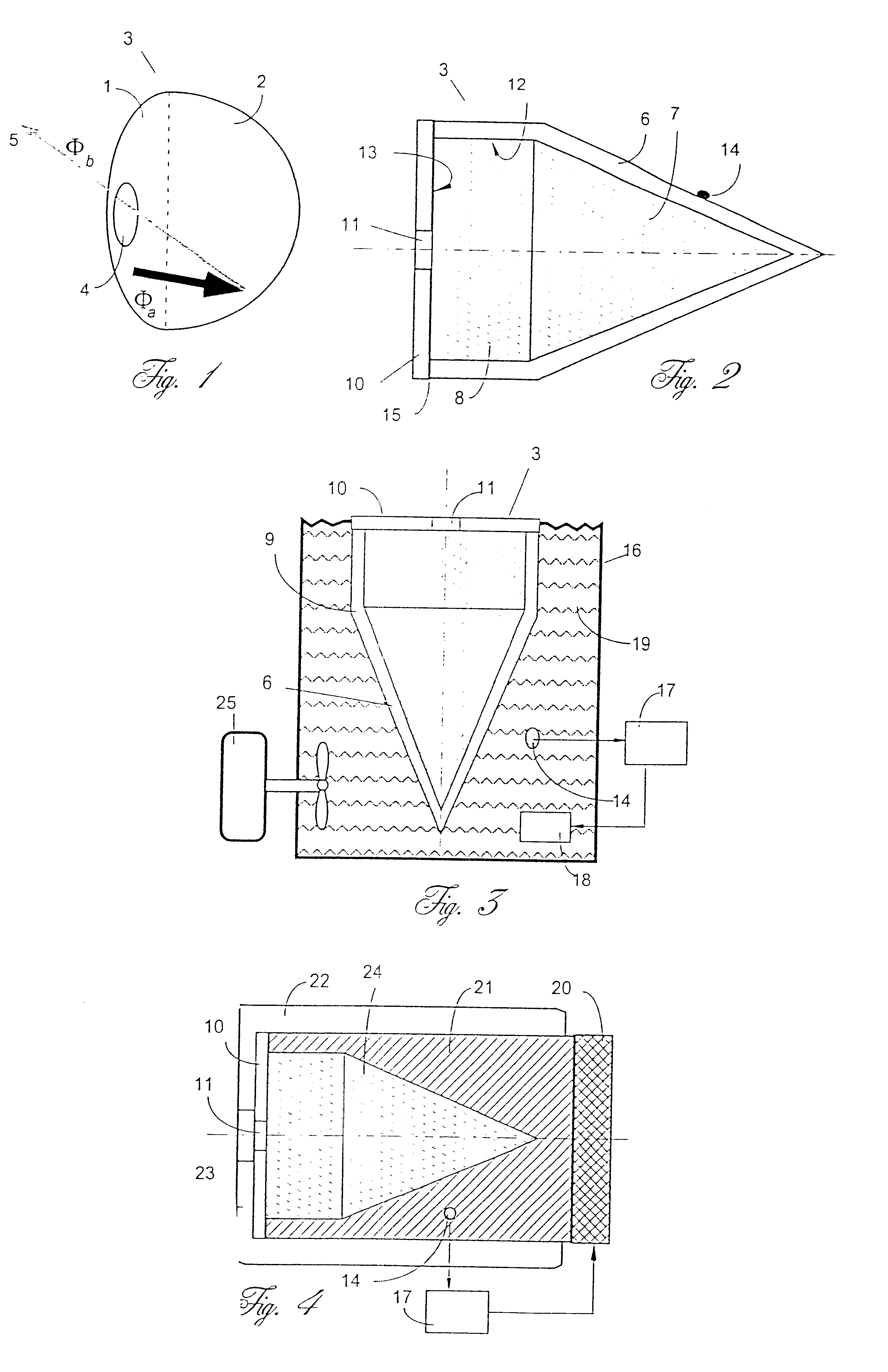
A blackbody cavity is disclosed having two types of wall surfaces wherein a first type has high emissivity and a second type has low emissivity. The low emissivity wall surface has an aperture from where the infrared radiation escapes the cavity, and is preferably shaped to minimize the escape through the aperture of radiation emanated directly from the low emissivity wall itself. The combination of high and low emissivity wall surfaces allows the blackbody to reduce the influence of the environmental temperature while maintaining emissivity approaching unity.

Problems solved by technology

This is not nearly enough to consider a painted surface as a blackbody.
A challenge to a blackbody designer is to provide a cavity having uniform wall temperatures with as many internal reflections as possible.
In many instances, this is not easy to accomplish, because any increase in cavity dimensions makes it much more difficult to assure the uniform wall temperatures, which for high precision blackbodies should not vary by more than 0.02.degree. C. over the entire cavity surface.
The most troublesome portion in the cavity is it's front end where the IR thermometer is inserted in the aperture.
Dimensions of the front end should allow placement of the thermometer probe into the cavity opening, which may affect cavity wall temperatures near the opening and subsequently degrade the effective emissivity.

Method used


Image

  • Blackbody cavity for calibration of infrared thermometers
  • Blackbody cavity for calibration of infrared thermometers

Examples


Embodiment Construction

Any surface is an emitter of thermal radiation. The properties of a surface are a key factor in determining how well the surface can emit such radiation. According to Kirchhoff's Law, a good emitter must be a poor reflector and vice versa:

.epsilon.+.rho.=1 (1)

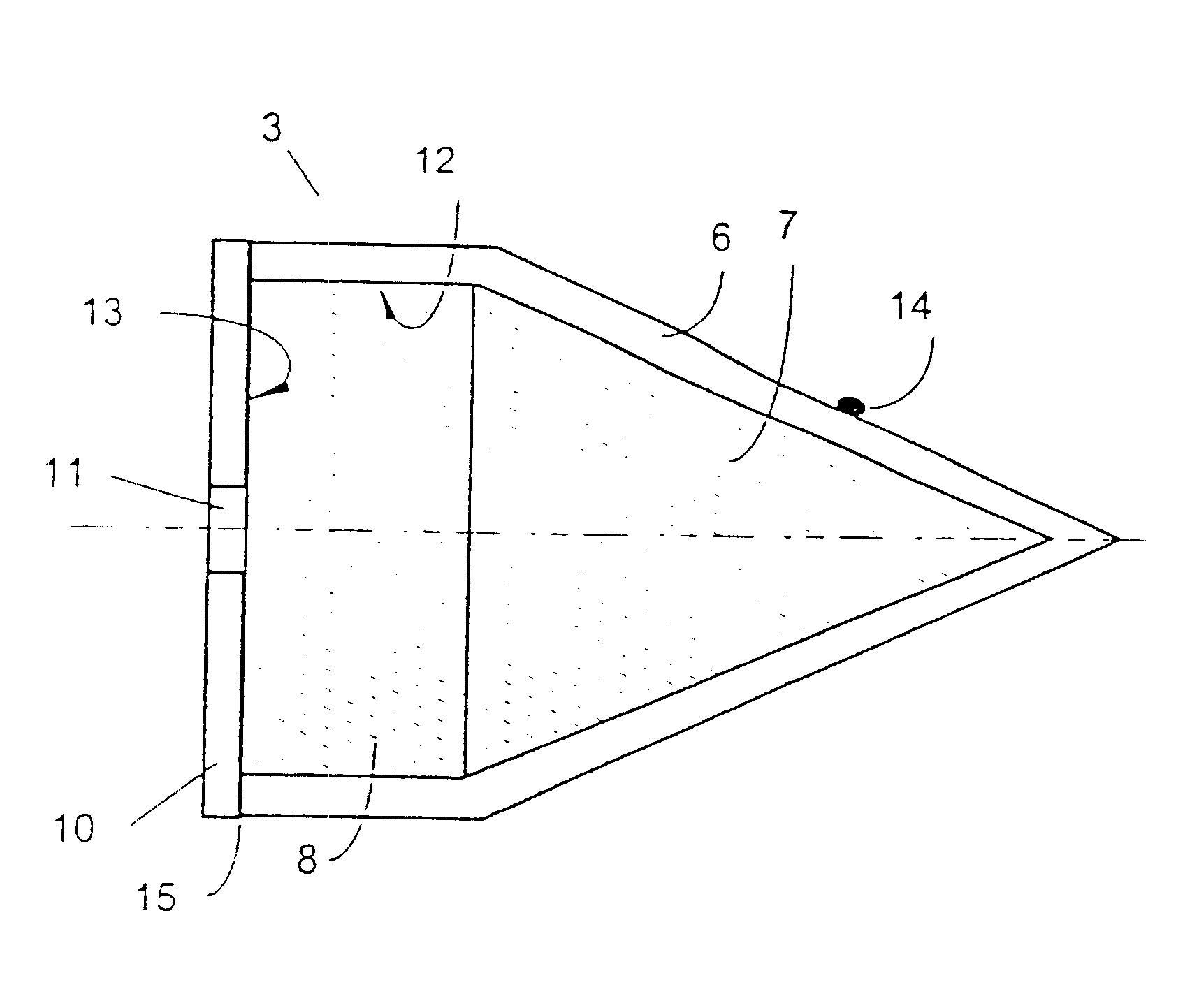
where .epsilon. is emissivity and .rho. is reflectivity of an object. Both factors vary on a scale from 0 to 1, with one factor changing at the expense of the other. Thus, a mirror is very poor emitter and a black surface is a very good emitter. FIG. 1 is a generalized or schematic representation of a two-surface blackbody cavity according to the present invention. The blackbody is an enclosure 3 consisting of two types of the inner surfaces, which may be termed first surface 1 and second surface 2. It should be understood that the type of the outside surface of enclosure 3 has no effect whatsoever on it's performance as a blackbody. The best performance, by definition, is when a blackbody doesn't reflect anything (.rho.=0) and...


PUM

PropertyMeasurementUnit
emissivityaaaaaaaaaa
temperaturesaaaaaaaaaa

Abstract

A blackbody cavity having two types of wall surfaces wherein a first type has high emissivity and a second type has low emissivity. The low emissivity wall surface has an aperture from where the infrared radiation escapes the cavity, and is preferably shaped to minimize the escape through the aperture of radiation emanated directly from the low emissivity wall itself. The combination of high and low emissivity wall surfaces allows the blackbody to reduce the influence of the environmental temperature while maintaining emissivity approaching unity.

Description

1. Field of the InventionThe present invention relates generally to test equipment for measuring electromagnetic emission in mid- and far-infrared spectral ranges and relates more specifically to a blackbody cavity for calibration of infrared thermometers.2. Description of Prior ArtTemperature of an object can be measured by means of thermal radiation when naturally emanated electromagnetic (thermal) radiation in the mid- and far-infrared (IR) spectral ranges is detected by an appropriate sensor. The IR sensor output signal is indicative of the surface temperature of an object. A sensor is an integral part of a measurement and / or data acquisition system. As a rule, a sensor is combined with some kind of an optical system which may include refractive and reflective components, such as lenses, mirrors, wave guides, windows, among others. A combination of optical components, an infrared sensor, and signal conditioning electronic circuits produces a useful signal which corresponds to th...

Claims


Application Information

Patent Timeline
Patent Type & Authority Patents(United States)
IPC IPC(8): G01J5/52
CPCG01J5/522G01J5/53
Inventor FRADEN, JACOB
Owner ADVANCED MONITORS
Learn More