
System and method to improve the overall performance of a wireless communication network

a wireless communication network and wireless communication technology, applied in the field of wireless communication network system performance improvement, can solve the problems of large latency associated with route discovery, large and often subject to change in the transmission path between mobile devices, so as to reduce the buffered information level, reduce the latency of route discovery between nodes, and reduce the effect of latency

Active Publication Date: 2006-08-24
STRONG FORCE IOT
View PDF10 Cites 18 Cited by
  • Summary
  • Abstract
  • Description
  • Claims
  • Application Information

AI Technical Summary

Benefits of technology

This approach significantly reduces latency and overhead in route discovery, minimizes packet buffering, and enhances network scalability by ensuring efficient route selection and reducing unnecessary network flooding, even when the destination node is not present.

Problems solved by technology

However, transmission paths between mobile devices are often subject to change as devices move, therefore ad-hoc network communication must be able to adapt to achieve optimum performance while addressing the limited capabilities and capacities of mobile individual devices.
There can be a large latency associated with this route discovery if the destination is several hops away.
This latency can be very large, particularly if an expanding ring search technique is used as is done in AODV.
Transceivers typically used in these networks are memory constrained and hence a big latency can force them to drop packets from the buffer.
The large latency can also be unsuitable for some applications especially the ones which use TCP.
The other drawback of the discovery process is the number of routing packets it generates / forwards during the process.
These networks can span in large areas and such broadcasting and forwarding can tremendously increase the latency as well as the overhead.
This overhead is even worse if the destination node does not even exist in the network, and in this case, the source node keeps repeating the discovery process and flooding the network in vain.

Method used


Image

  • System and method to improve the overall performance of a wireless communication network
  • System and method to improve the overall performance of a wireless communication network
  • System and method to improve the overall performance of a wireless communication network

Examples


Embodiment Construction

[0022] The embodiments of the present invention described below improves the system performance of a wireless network by controlling the dissemination of Routing packets and decreasing the latency in finding routes. In doing so, each embodiment serves to eliminate the need to keep large buffers in each Subscriber Device (SD).

[0023] As noted above, wireless networks frequently use On-Demand protocols (e.g. AODV (RFC 3561), DSR (Internet Draft), and so forth) as the routing protocol. Typically the Route Discovery involves broadcasting and forwarding of RREQ packets until the route is found. All the application packets generated in the mean time are buffered at the source node and there typically is a large latency associated with this route discovery if the destination is several hops away. The embodiments described below include a system and method to discover the routes to the destination in an efficient way and also decrease the latency involved in finding the route.

[0024] As des...


PUM


Abstract

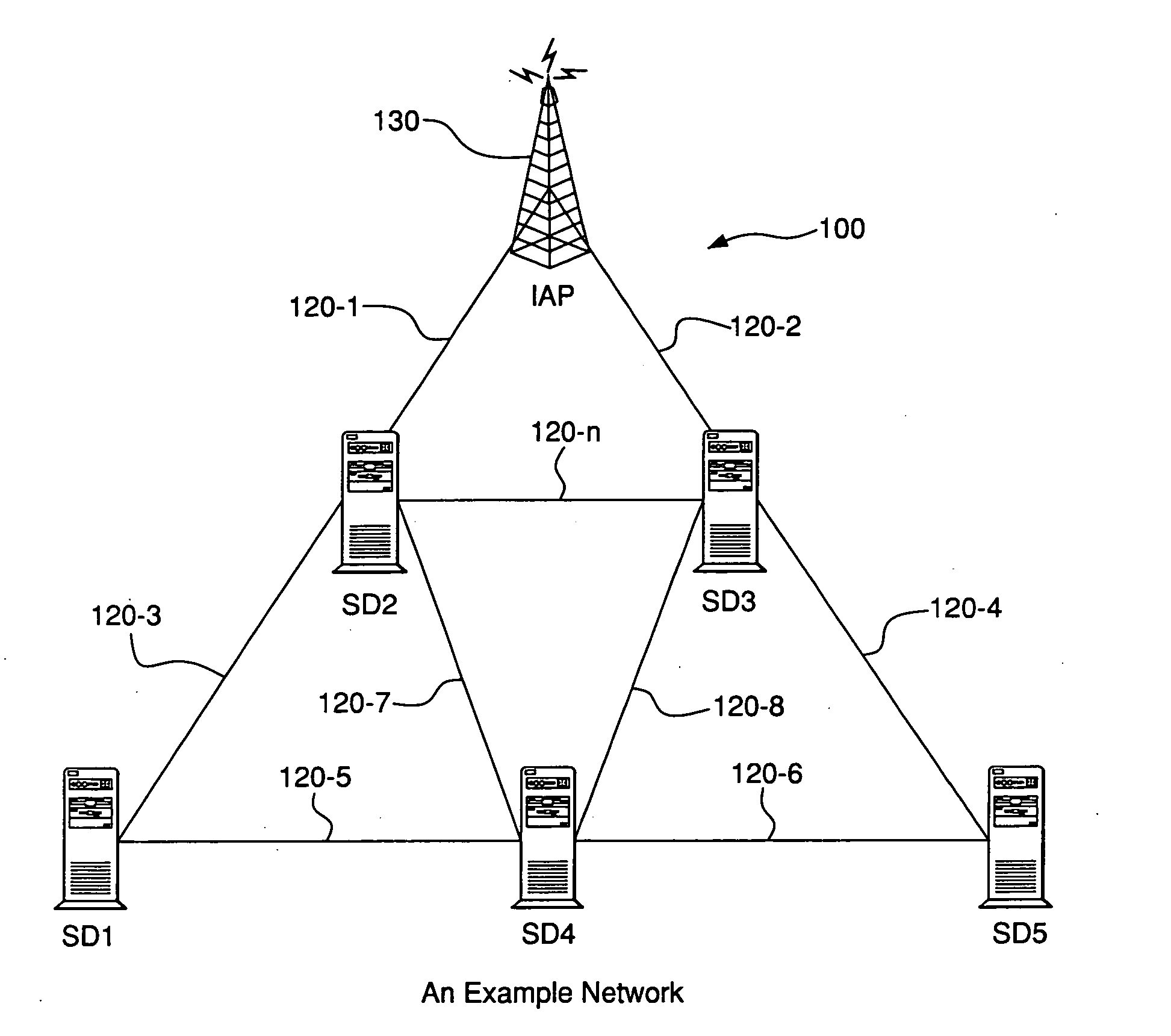
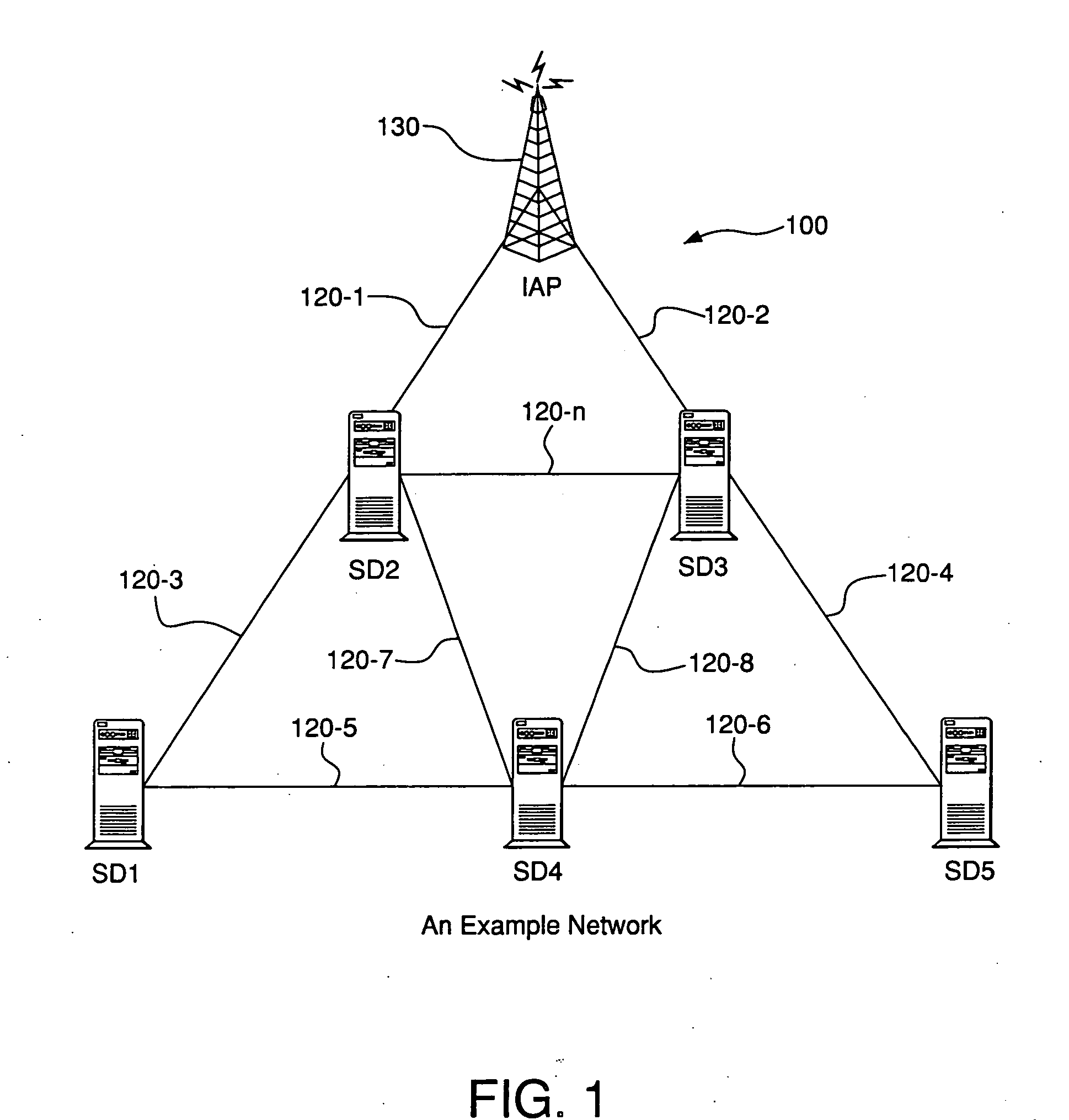
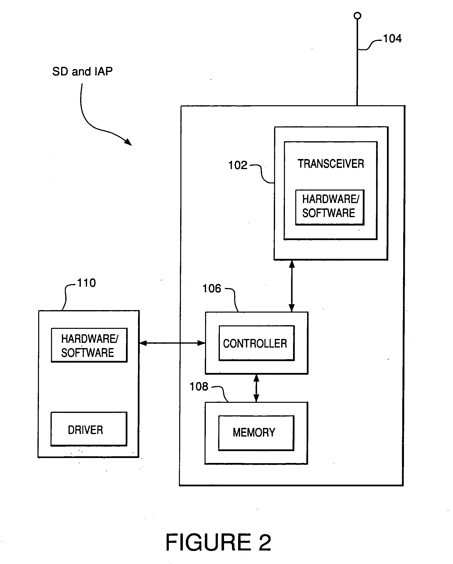
A system and method for controlling the dissemination of Routing packets, and decreasing the latency in finding routes between nodes (SD1 through SD5). The system and method provides message exchanges between wireless devices (SD1 though SD5, IAP 130) to determine optimized communication routes with a minimum of overhead messages and buffered data. Exchanged messages are reduced to a specific series of exchanges indicating destination, destination node detection, and route, preferably using a series of IAP devices. Routes are discovered in an efficient manner and latency in finding routes between nodes (SD1 though SD5) is reduced, thereby reducing buffered information levels at individual devices.

Description

[0001] This application claims benefit under 35 U.S.C. §119(e) from U.S. Provisional Patent Application Ser. No. 60 / 476,236, filed on Jun. 6, 2003, the entire content of which is incorporated herein by reference.BACKGROUND OF THE INVENTION [0002] 1. Field of the Invention [0003] The present invention relates to a system and method for improving the system performance of a wireless communication network by controlling the dissemination of Routing packets, and decreasing the latency in finding routes between nodes. Specifically, the present invention provides a system and method of message exchanges to determine optimized communication routes with a minimum of overhead messages and buffered data. [0004] 2. Description of the Related Art [0005] Wireless communication networks, such as mobile wireless telephone networks, have become increasingly prevalent over the past decade. These wireless communications networks are commonly referred to as “cellular networks”, because the network inf...

Claims


Application Information

Patent Timeline
Patent Type & Authority Applications(United States)
IPC IPC(8): H04Q7/00H04Q7/24H04L12/56H04W40/02H04W40/24H04W40/26H04W48/08H04W84/18H04W88/04H04W88/08H04W92/18
CPCH04L45/02H04L45/121H04W40/02H04W40/20H04W40/24H04W40/246H04W40/248H04W40/26H04W48/08H04W84/18H04W88/04H04W88/08H04W92/18
Inventor JOSHI, AVINASH
Owner STRONG FORCE IOT
Learn More