Garment steamer with standby heater

a standby heater and steam generator technology, applied in the direction of cleaning equipment, lighting and heating equipment, container discharge methods, etc., can solve the problems of single element boiler mechanism affording significant problems, cyclical output of high to low steam, and exhausting steam on prior art appliances

Inactive Publication Date: 2006-08-24
CONAIR CORP
View PDF4 Cites 27 Cited by
  • Summary
  • Abstract
  • Description
  • Claims
  • Application Information

AI Technical Summary

Benefits of technology

[0013] The present invention is directed to a novel heater and heater control design for a garment steamer that features a low-powered standby setting parallel to a high powered steam setting. The invention also features a convenien...

Problems solved by technology

Also, steam has been exhausted on prior art appliances through a remote hand piece, while the heater controls have been mounted on the main housing, which has been supported on the tabletop or the floor not readily accessible to the user.
The single element boiler mechanism affords a significant problem.
This interruption generally results in a cyclical output of high to low steam.
Another problem encountered in prior art garment steamers, with a large steam volume, is that the units operate continuously, even while the steam is not being used, such as between applications.
There ...

Method used


Image

  • Garment steamer with standby heater
  • Garment steamer with standby heater
  • Garment steamer with standby heater

Examples


Embodiment Construction

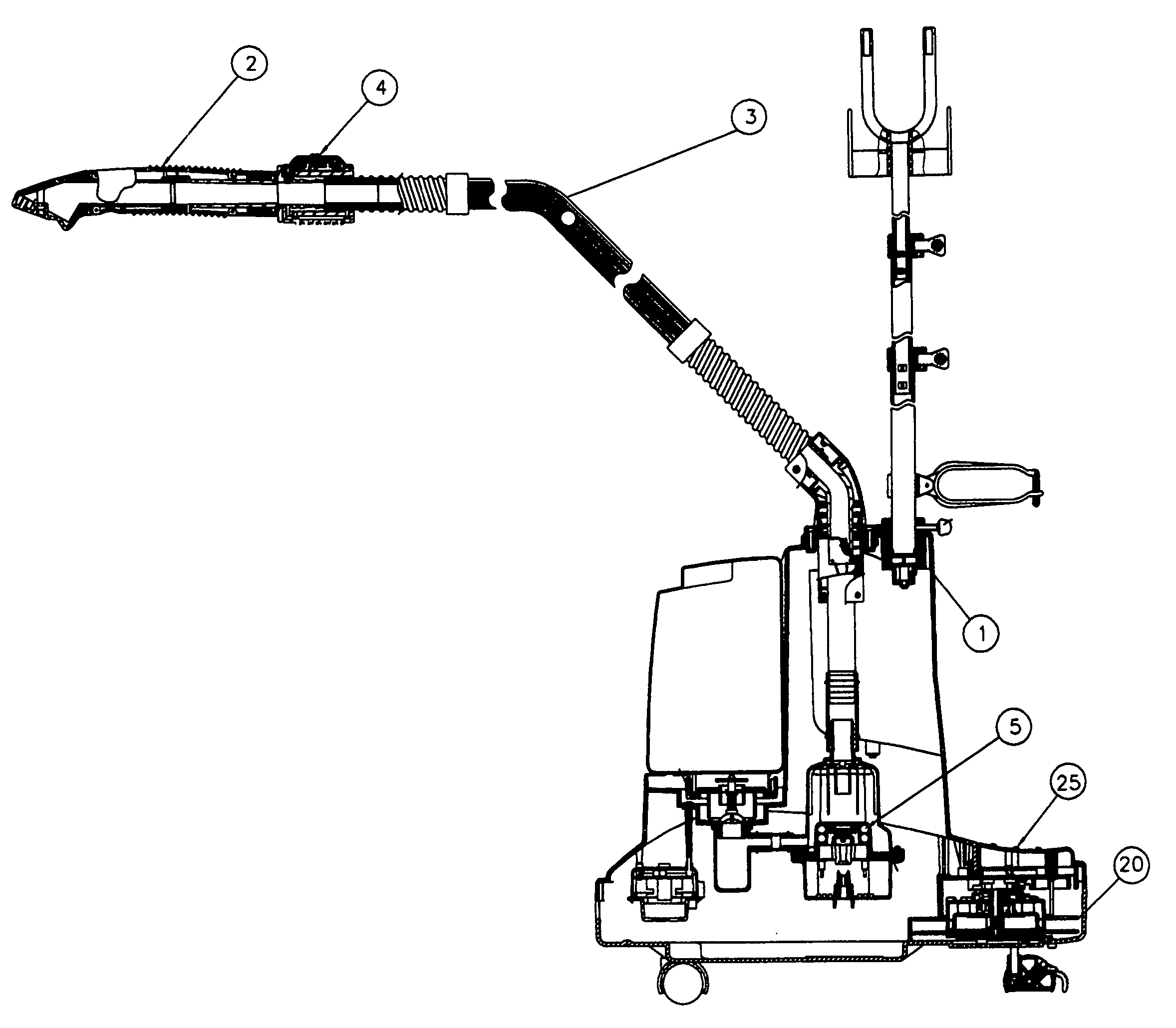
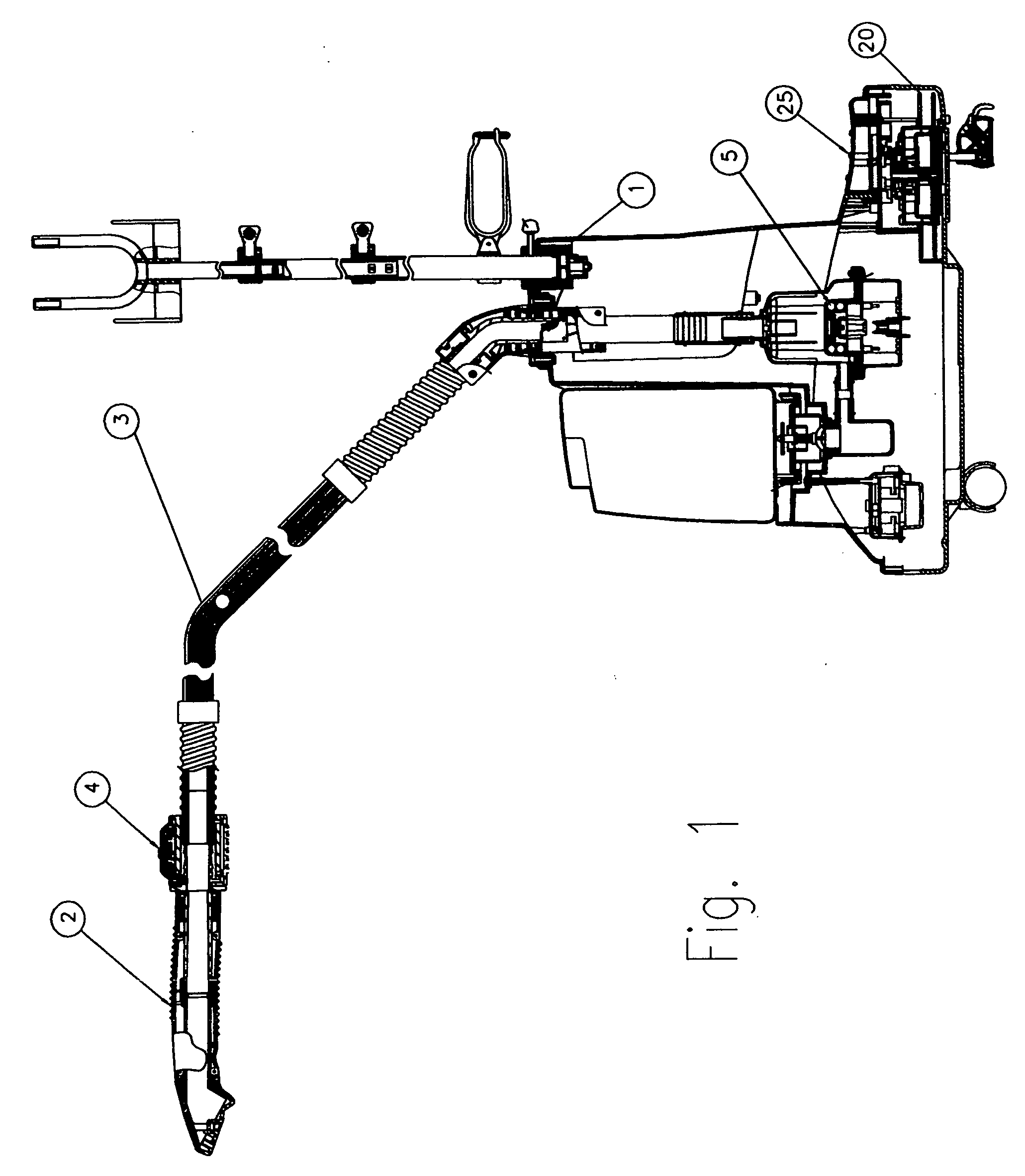
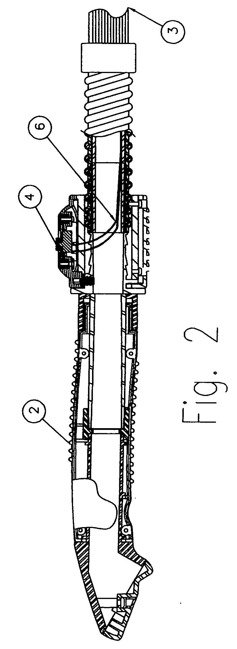
[0027] Referring to FIGS. 1 to 4, the present invention, of an improved garment steamer, is illustrated. The assembled steamer houses the boiler 5, which supplies steam thru hose 3 to the hand piece 2. At the base of the hand piece 2 is a switch 4 that switches between two pair of contacts 7, 8 on the boiler assembly 5 in order to power one or both of the heaters 9, 10 which are cast into the boiler assembly 5. The circuit diagram in FIG. 10 represents a circuit similar to that employed in the preferred embodiment. The preferred circuit switches a high-powered heater 10, (approximately 1600 Watts), via switch 4 and relay 13 and parallel to the low powered, standby, heater 9, (at approximately 200 Watts). The standby heater 9 is powered only through the primary power switch 11 on the main housing 1. The proportion between the power ratings of the two heaters will vary depending on the geometry and volume of the components.

[0028] The parallel heaters can also be controlled by separat...


PUM


Abstract

A garment steaming device having a novel heater and heater control design for a garment steamer that features a low-powered standby setting parallel to a high powered steam setting. The invention also features a convenient switch location to activate the high-powered heater, thereby selecting and controlling the steam and the standby feature. Furthermore the clothes steamer features a retractable cord reel, which can be easily activated with a foot switch.

Description

CROSS-REFERENCE TO RELATED APPLICATIONS [0001] This application claims priority to U.S. Provisional Patent Application Ser. No. 60 / 638,146 filed on Dec. 22, 2004, incorporated herein by reference in its entirety.BACKGROUND OF THE INVENTION [0002] 1. Field of the Invention [0003] The present invention relates to an electric steam generator and, more particularly, to an electric steam generator with a hose and wand, for use in removing wrinkles from garments and cloth hangings. [0004] 2. Description of Related Art [0005] It is known in the art to provide an electrical boiler, in a reservoir fed appliance, to supply continuous steam through a flexible tube to a hand-held wand. Such prior art appliances have been used to steam the wrinkles out of garments and cloth hangings. These prior art steamers have been made with single element boilers. Also, steam has been exhausted on prior art appliances through a remote hand piece, while the heater controls have been mounted on the main housin...

Claims


Application Information

Patent Timeline
IPC IPC(8): A61H33/12D06F75/00F17C7/04
CPCA47L25/00D06F75/12D06F75/30D06F87/00F22B1/284
Inventor CARLUCCI, VITO JAMES
Owner CONAIR CORP
Why Eureka
Try Eureka