Recreational structure using a coupling member

Inactive Publication Date: 2006-08-24
CA06
View PDF76 Cites 30 Cited by
  • Summary
  • Abstract
  • Description
  • Claims
  • Application Information

AI Technical Summary

Benefits of technology

[0005] The subject matter disclosed herein provides a technique for joining structural components o

Problems solved by technology

While the horizontal and vertical frame portions of a trampoline could be fabricated to be one unitary structure, suc

Method used


Image

  • Recreational structure using a coupling member
  • Recreational structure using a coupling member
  • Recreational structure using a coupling member

Examples


Embodiment Construction

[0020] It should be understood that the word “exemplary” is used herein to mean “serving as an example, instance, or illustration.” Any embodiment described herein as “exemplary” is not necessarily to be construed as preferred or advantageous over other embodiments.

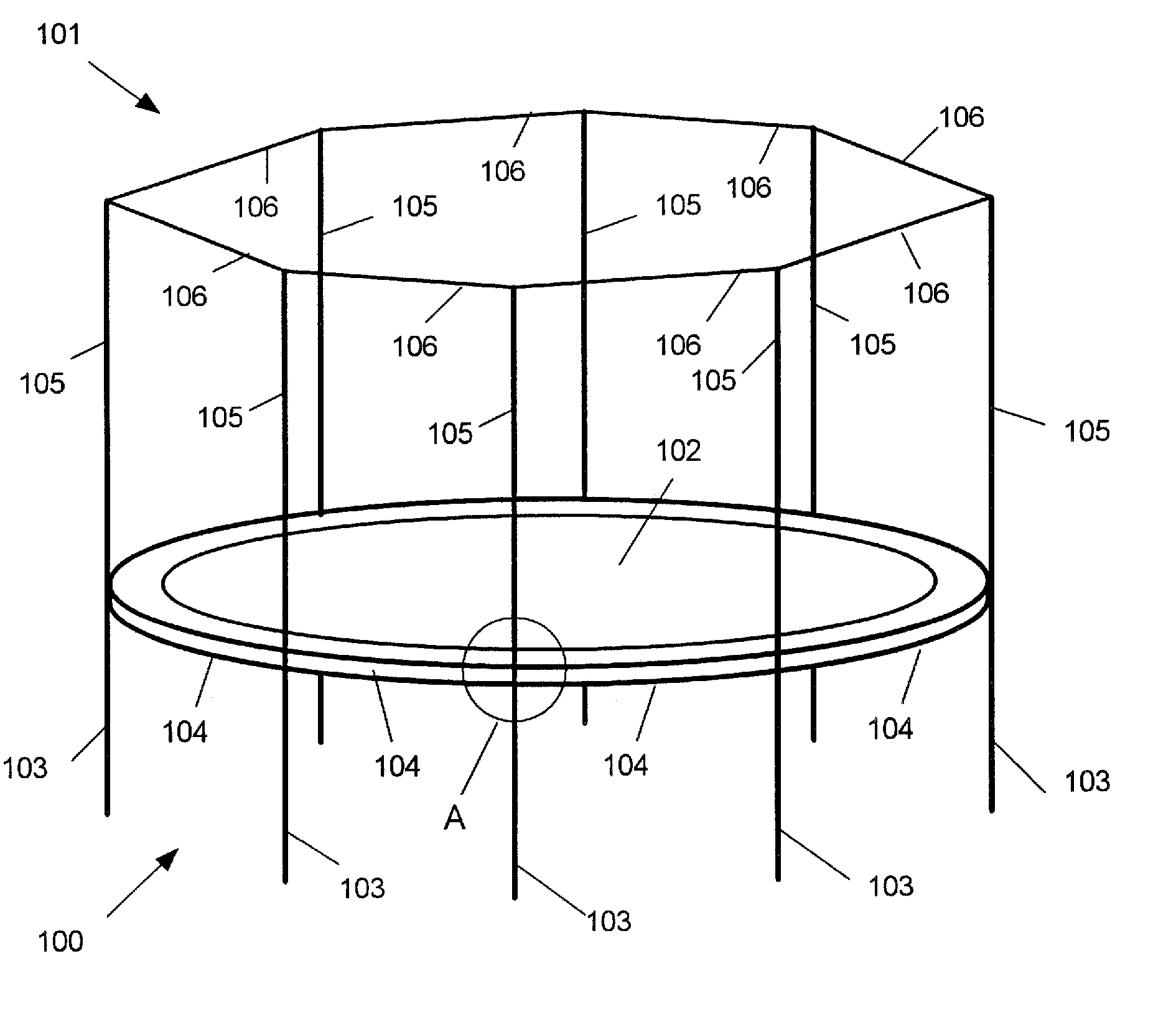
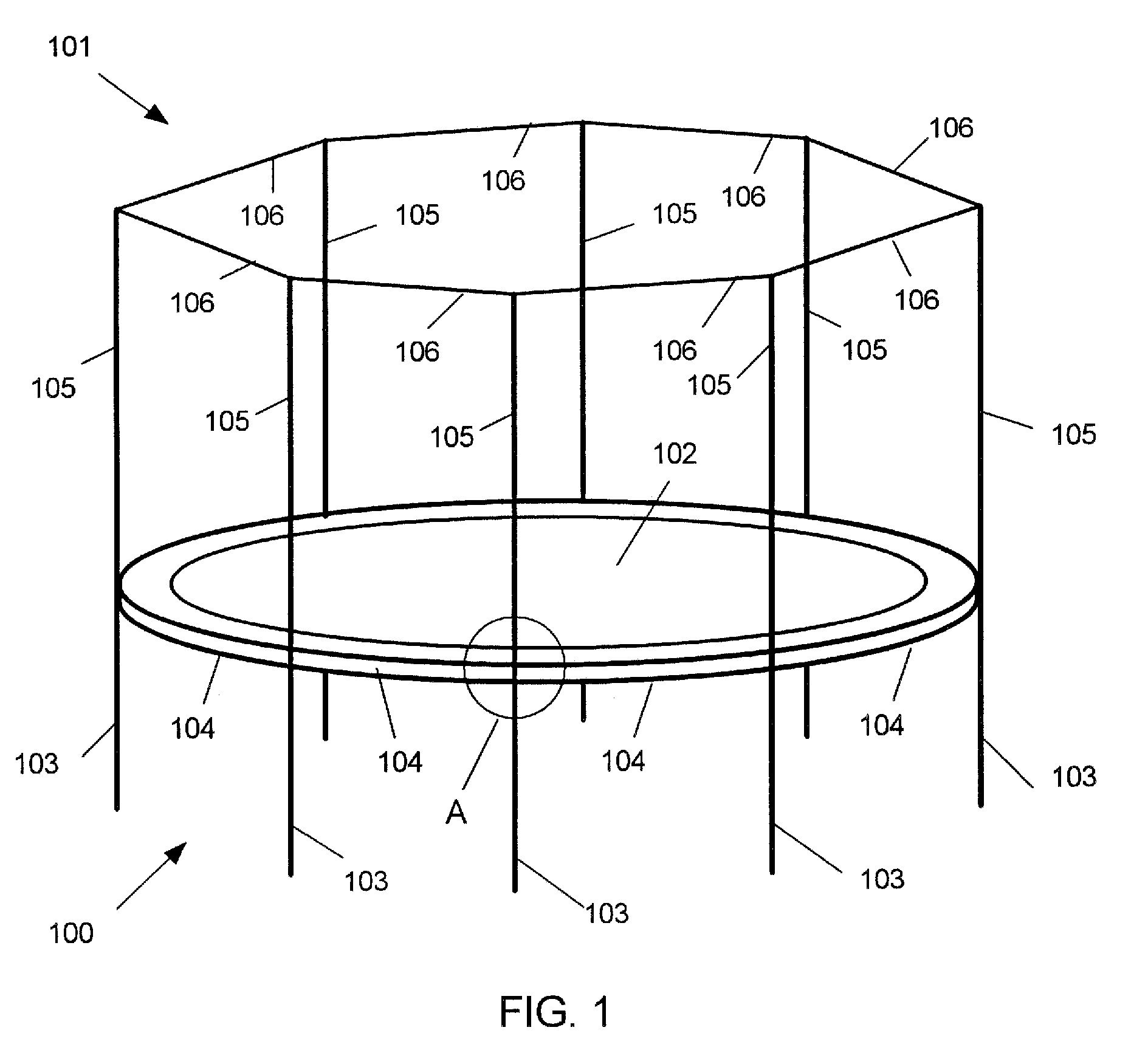
[0021]FIG. 1 depicts a perspective view of an exemplary trampoline 100 having an exemplary safety enclosure 101. Trampoline 100 includes a rebounding surface 102 and a frame structure having vertical frame members 103 and a circular frame that can be formed from a plurality of circular frame members 104. Vertical frame members 103 and circular frame members 104 are typically made from hollow metal tubing having sufficient strength to bear the stresses and loads that are associated with trampolines. Safety enclosure 101 includes a frame structure having vertical pole members 105 and horizontal support members 106. A horizontal support member 106 is connected between adjacent vertical pole members in a substantially inflex...


PUM


Abstract

A recreational structure, such as a trampoline frame, can be quickly and reliably assembled using a coupling member generally having a “T” configuration. A first arm member and a second arm member are disposed in an opposite relationship with each other. The first and second arm members each receive one end of a horizontal frame member of the recreational structure. The third arm member includes flange members that receive one end of a vertical frame member of the recreational structure and one end of a vertical pole member of, for example, a safety enclosure.

Description

CROSS-REFERENCE TO RELATED APPLICATION [0001] The present patent application is a continuation-in-part patent application of U.S. patent application Ser. No. 10 / 908,469, filed May 12, 2005, entitled “Recreational Structure Using a Sleeve Joint Coupling,” invented by Craig Adams, which is a continuation-in-part (CIP) patent application of U.S. patent application Ser. No. 10 / 905,105, filed Dec. 15, 2004, entitled “Recreational Structure Using A Sleeve-Joint Coupling,” invented by Craig Adams, both of which are incorporated by reference herein.BACKGROUND [0002] The subject matter disclosed herein relates to recreational structures. More particularly, the subject matter disclosed herein relates to a frame arrangement for a recreational structure, such as a trampoline, that uses a coupling member. DESCRIPTION OF THE RELATED ART [0003] Recreational structures having frames, such as trampolines, are well-known. For example, a trampoline has a horizontal frame to which a rebounding surface ...

Claims


Application Information

Patent Timeline
IPC IPC(8): A63B5/11A63B9/00
CPCA63B5/11A63B9/00A63B71/022A63B2210/50
Inventor VANELVERDINGHE, JEFFRY L.ADAMS, CRAIG
Owner CA06
Why Eureka
Try Eureka