
Surgical illumination device and method of using

a surgical and illumination device technology, applied in the field of surgical illumination devices, can solve the problems of high manufacturing cost of lighting systems, pain, and potential infection of patients, and achieve the effects of improving patient comfort, reducing the risk of infection, and improving the quality of surgical illumination

Inactive Publication Date: 2006-08-24
MINNESOTA SCI
View PDF14 Cites 14 Cited by
  • Summary
  • Abstract
  • Description
  • Claims
  • Application Information

AI Technical Summary

Problems solved by technology

Any incision results in some amount of trauma to the patient, including pain, potential infection, healing time and dysfunction.
A problem that exists with operating through a minimal incision, however, is providing sufficient illumination to enable the physician to see what he / she is doing.
Because a woven optical fiber panel lighting system requires hand labor to manufacture, such a lighting system is expensive to manufacture.
The Lumitex® retractor, as well as other lighted retractors, are also specific to certain retractor designs and not readily usable on varying sizes and retractor types.
Further, these retractors take up a great deal of space in the wound, thus requiring larger incisions and making the surgeon's job more difficult.
Finally, these light types are not readily moved from retractor to retractor after initial placement.

Method used


Image

  • Surgical illumination device and method of using
  • Surgical illumination device and method of using
  • Surgical illumination device and method of using

Examples


Embodiment Construction

Definitions

[0024]“Pull Force” refers to an amount of force required to remove a first object from a second object to which the first object is attached.

NOMENCLATURE

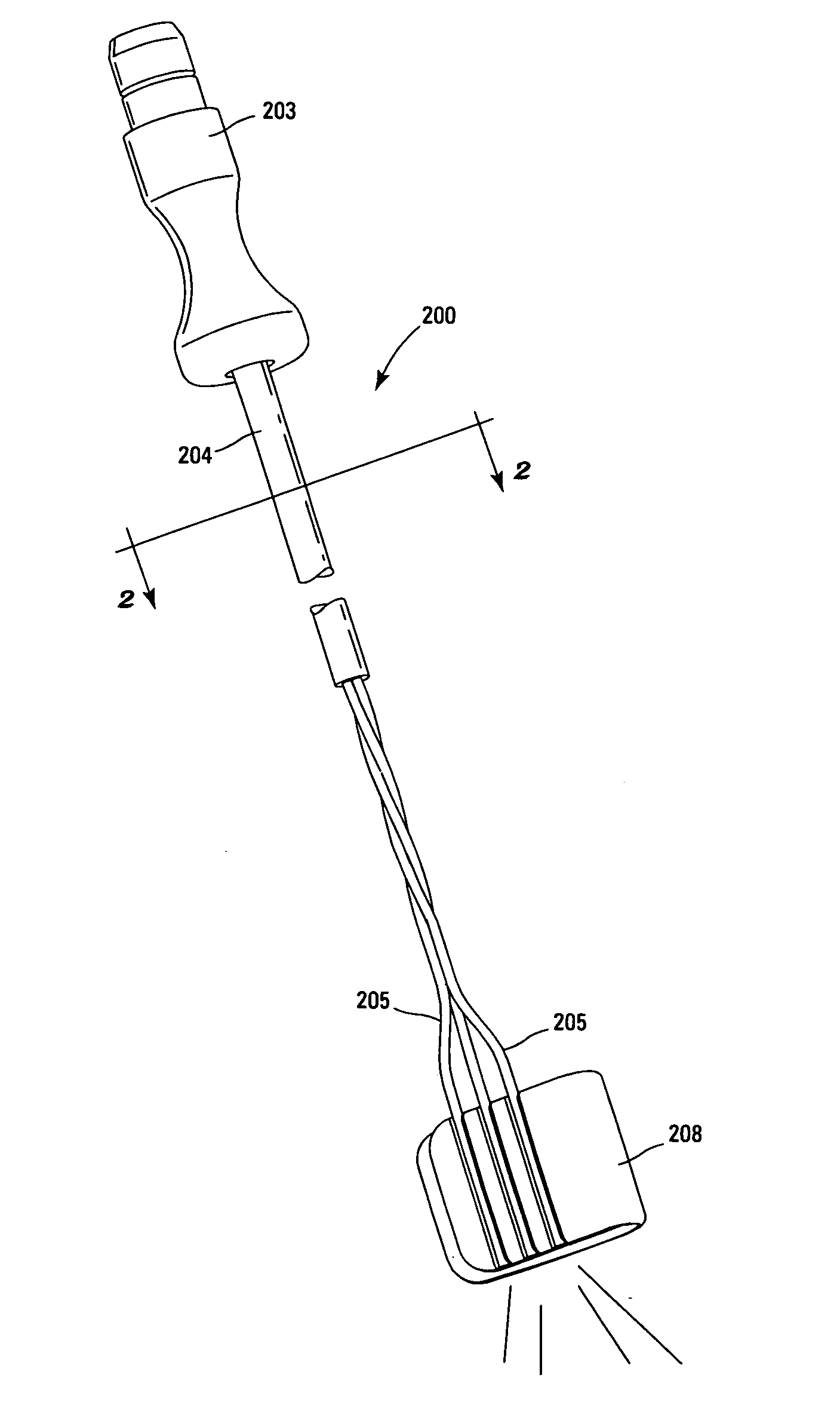
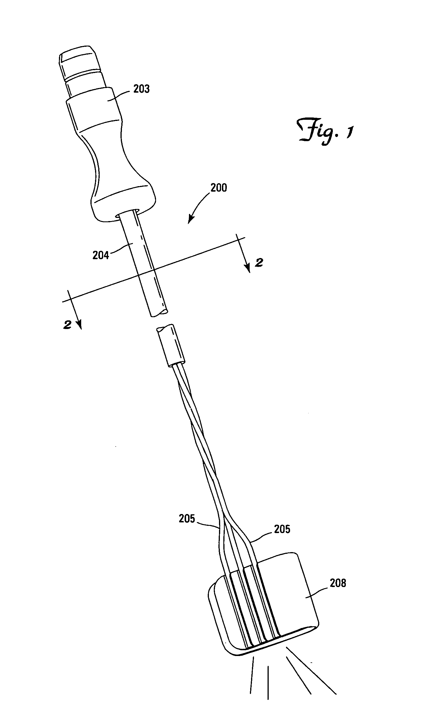
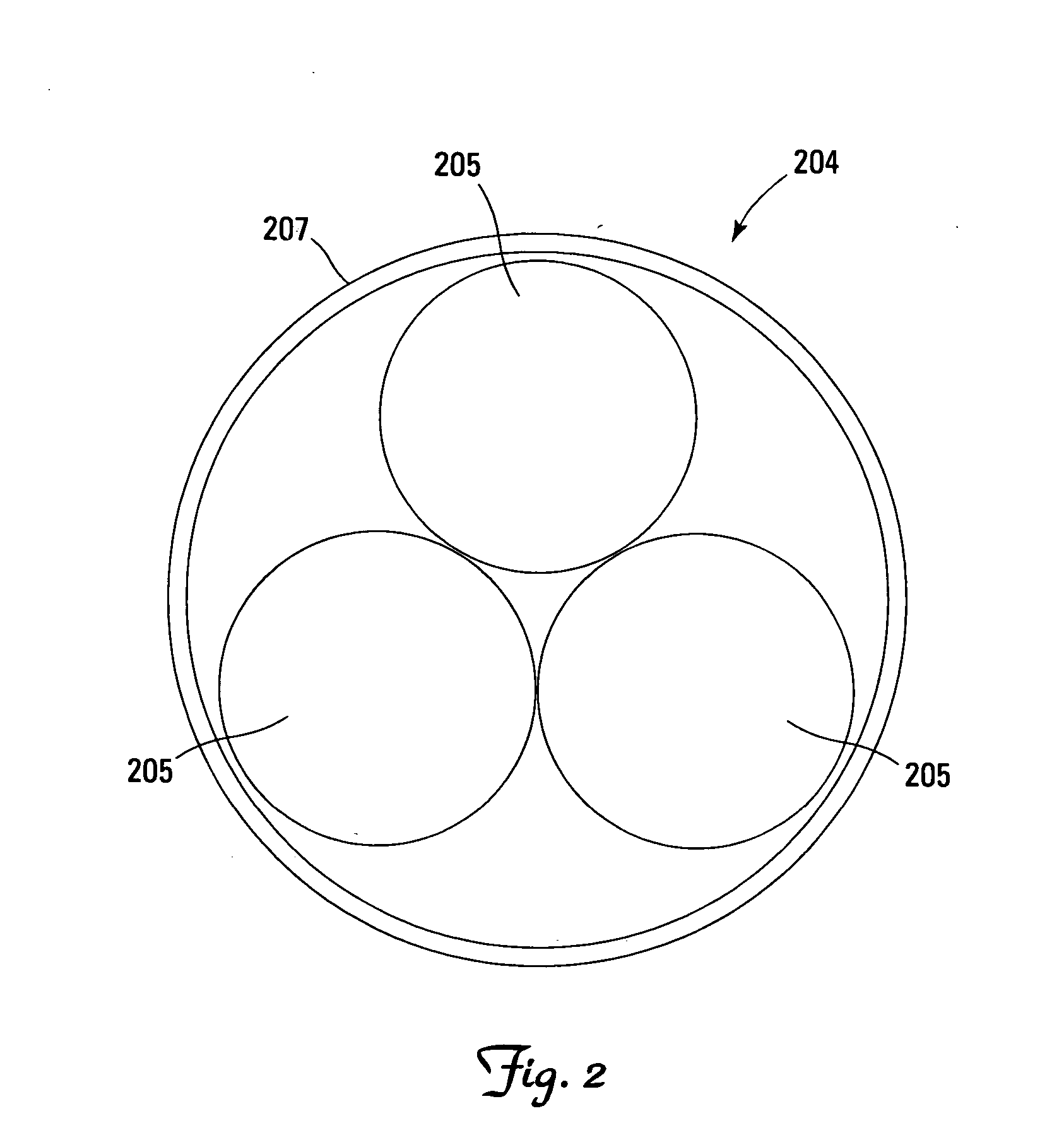
[0025]200 Surgical Illumination Device [0026]202 Light Source [0027]203 Connector [0028]204 Light Conducting Fiber Bundle [0029]205 Light Conducting Fiber [0030]206 Retractor Blade [0031]207 Sheath [0032]208 Clip [0033]209 First End of Clip [0034]210 Retaining Channel [0035]211 Second End of Clip [0036]213 Gap [0037]215 First Major Surface [0038]300 Surgical Illumination Device [0039]302 Light Source [0040]304 First Major Surface [0041]305 Adhesive [0042]306 Second Major Surface [0043]308 Pad [0044]310 Pressure Sensitive Adhesive [0045]400 Surgical Illumination Device [0046]407 Adhesive [0047]408 Clip [0048]409 First End of Clip [0049]411 Second End of Clip [0050]413 Gap [0051]415 First Major Surface [0052]600 Surgical Illumination Device [0053]602 First Major Surface [0054]604 Second Major Surface [0055]606 Retaining...


PUM


Abstract

A surgical illumination device and method of using includes a mounting platform attachable to a surgical device and light conducting fibers attached to the platform.

Description

[0001] This Application claims the benefit of Provisional Patent Application 60 / 655,153 filed Feb. 22, 2005 and is herein incorporated by reference in its entirety.FIELD OF THE INVENTION [0002] The invention relates to a surgical illumination device for lighting an exposed area during medical or surgical treatment. The device is separately attachable to a variety of surgical or medical devices. BACKGROUND [0003] Medical treatment often requires a surgeon to create an incision in a patient to access the anatomical site requiring treatment. Any incision results in some amount of trauma to the patient, including pain, potential infection, healing time and dysfunction. A smaller incision generally reduces trauma and is thus a goal of all surgical treatment. In order to most effectively access the interior of a patient, retractor systems have been developed which allow a physician sufficient anatomical access while minimizing patient trauma through a smaller incision. A system developed ...

Claims


Application Information

Patent Timeline
Patent Type & Authority Applications(United States)
IPC IPC(8): A61B1/06
CPCA61B1/32A61B17/02A61B19/52A61B2019/5206A61B90/36A61B2090/306
Inventor SHARRATT, TODD W.WALD, RONALD S. VON
Owner MINNESOTA SCI
Learn More