Positioning vehicle for positioning a test probe

Inactive Publication Date: 2006-08-31
BAM
View PDF8 Cites 6 Cited by
  • Summary
  • Abstract
  • Description
  • Claims
  • Application Information

AI Technical Summary

Benefits of technology

[0039] Alternatively in place of the air cylinder one may also apply a magnetic lift

Problems solved by technology

However the operation of the measurement apparatus changes on account of the fatigue of the personnel, which may considerably compromise the measure

Method used


Image

  • Positioning vehicle for positioning a test probe
  • Positioning vehicle for positioning a test probe
  • Positioning vehicle for positioning a test probe

Examples


Embodiment Construction

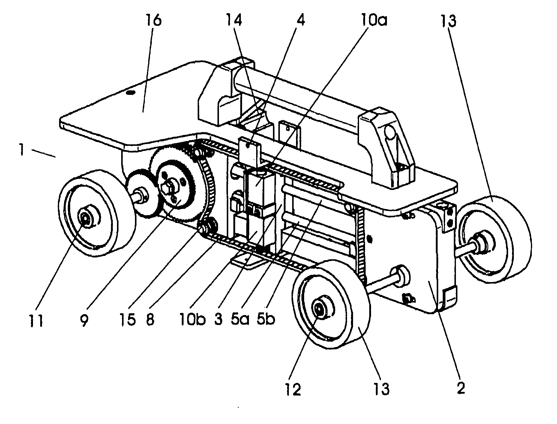
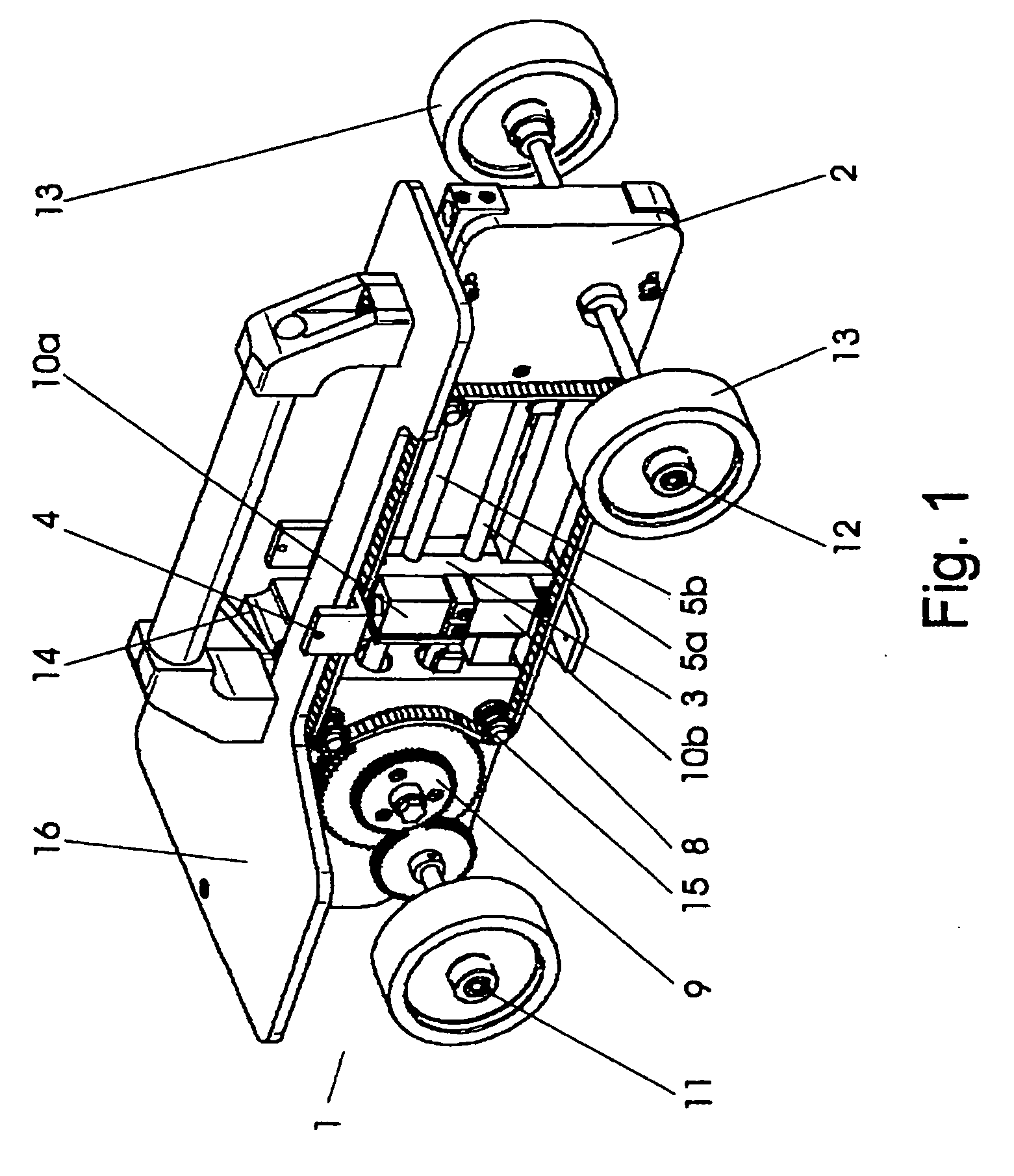
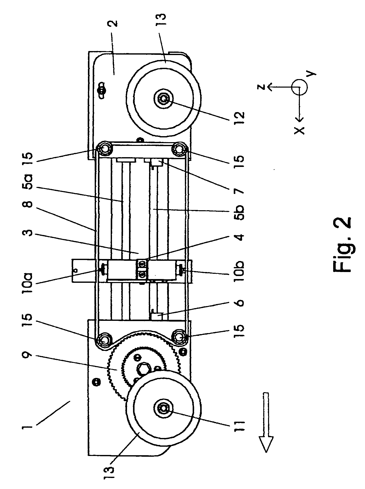
[0045] FIGS. 1 to 3 show a positioning vehicle according to the invention in several views. The positioning vehicle 1 contains a traveling vehicle base part 2 with a guide device 3 and with a test probe carrier 4 which is guided in a guide 5 by this guide device 3.

[0046] The vehicle base part 2 contains a first axle 11 and a second axle 12 on which in each case two wheels 13 are attached. These axles are arranged parallel to one another and are located at the outer ends of the vehicle base part 2. At the same time the second axle 12 is designed in a particularly wide manner compared to the first axle 11. The arrangements of the axles in the front and rear region of the vehicle base part, as well as the wide design of the second axle serve for providing the positioning vehicle with an adequate stability against tilting. In this embodiment example, the travel line of the positioning vehicle is predefined by the arrangement of the two axles. The positioning vehicle may be displaced al...


PUM


Abstract

Described is a method for operating a positioning vehicle for positioning a test probe in defined intervals along a travel line, as well as to a positioning vehicle for carrying out the method. The positioning vehicle contains a traveling vehicle base part with a guide device and with a test probe carrier guided by this guide device in a guide. The guiding has a first reversal point and a second reversal point. The guide device comprises guide means in order on displacing the vehicle base part to guide the test probe carrier in the travel direction up to the first reversal point after it has reached the second reversal point, and in order to lead back the test probe carrier opposite to the travel direction up to the second reversal point after it has reached the first reversal point. In the phase of the return, the test probe carrier relative to the vehicle base part has the negative speed of the vehicle base part. Described is also a device which permits in particular objects having large surfaces to be scanned with little effort.

Description

BACKGROUND OF THE INVENTION [0001] The invention relates to a method for operating a positioning vehicle for positioning a test probe at defined distances along a travel line, and to a positioning vehicle for carrying out the method. [0002] In the building industry it is often necessary to inspect the quality of a building construction. At the same time it may also be useful to inspect the quality of the construction during its phase of being built as well as after completion of the building work. Such an inspection, in particular with tunnels and bridges, is obligatory. [0003] It is known to test building constructions by way of methods which are based on sound. Counted amongst these are the ultrasonic measurement method and the impact echo method. These methods are for example applied for determining the thickness of concrete parts, for localizing prestressing cuts and for locating defect locations. Both methods may be used individually and independently, or in combination, for re...

Claims


Application Information

Patent Timeline
IPC IPC(8): G01D11/00G01N29/26
CPCG01N29/225G01N29/2493G01N2291/0421G01N2291/044
Inventor WIGGENHAUSER, HERBERTSCHAURICH, DIETER
Owner BAM
Why Eureka
Try Eureka