Method for Rapid Insulation of Expanses

a technology of rapid insulation and expanses, which is applied in the direction of liquid transfer devices, combustion types, lighting and heating apparatus, etc., can solve the problems of air leakage, air leakage, and adhesion of foam to the surface of the foam

Active Publication Date: 2006-08-31
ICP CONSTR INC
View PDF6 Cites 50 Cited by
  • Summary
  • Abstract
  • Description
  • Claims
  • Application Information

AI Technical Summary

Benefits of technology

[0011] Accordingly it is a principal object of the invention to provide a portable system that allows the operator to rapidly insulate the desired surface over a broad range of temperature and environmental factors.
[0012] It is another object of this invention to provide a system for insulating the desired surface in a time-efficient and quick manner, by providing a wide angle spray nozzle for the foam dispensing gun that allows for maximum spray coverage area.
[0013] It is yet another object of this invention to provide a system for rapidly insulating the desired surface in cold environments, more specifically in environments wherein the temperature of the ambient air and / or the desired surface area intended to be sprayed with the insulating foam is at or above 200 Fahrenheit.
[0014] The above mentioned objects are achieved in the invention by providing a system comprised of two pressurized tanks for the storage of the chemicals necessary for the two-part froth spray foam, tubing preferably lined with heating elements to transport the chemicals from the pressurized tanks, and a spray gun which combines the chemicals from the two pressurized tanks and sprays the froth foam insulation through a specially designed fan-type nozzle with optimal spray coverage area. The elements of the system combine to allow rapid application of spray insulation under the extreme environmental conditions that are often present at construction sites where the system will most commonly be utilized. The system can be used to apply spray insulation to a variety of surfaces, including but not limited to exterior walls, interior walls, spaces between 2×4's, ceilings, and floors. The surface being sprayed is not limited to any texture, material, substrate, or shape, and can be regular or irregular in geometry, have crevices, voids, or holes, and have or not have wires, pipes, and other building materials within. In general, the polyurethane spray foam will bond with any material or substrate that can be painted.
[0016] The second element of the rapid spray insulating system is the transfer lines or tubes that are used to transport the chemical components for the spray froth foam insulation to the dispensing gun. The tubing will ideally have one or more heating elements that run along the length of the hose. The heating elements are powered by a standard 120V / 60 Hz outlet, and can be plugged in to any common household or building outlet, or any construction site 120V electrical feed line. The tubing is lightweight, portable, and durable. The hose can be of any length, optimally yet preferably sheathed with a fiberglass weave, with a generally accepted maximum length of 200 feet. No pumps or motors are required to force the chemical components of the two-part foam through the tubes towards the spray gun.

Problems solved by technology

Pressure differences between the inside and outside of an enclosure cause air leakage to occur.
Air leakage contributes to warm air leaving an insulated area and cold air entering the area and can occur through cracks, gaps, openings, or through porous walls and insulation.
The presence of high humidity in the environment or moisture on the surface being sprayed degrades the adhesion of the foam to the surface, disrupting the complete bonding to the desired surface and allowing the foam to be easily peeled off the wall.
Cold temperatures have the same affect on the foam, causing the moisture on the substrate to freeze into ice crystals, disrupting bonding to the desired surface.

Method used


Image

  • Method for Rapid Insulation of Expanses
  • Method for Rapid Insulation of Expanses
  • Method for Rapid Insulation of Expanses

Examples


Embodiment Construction

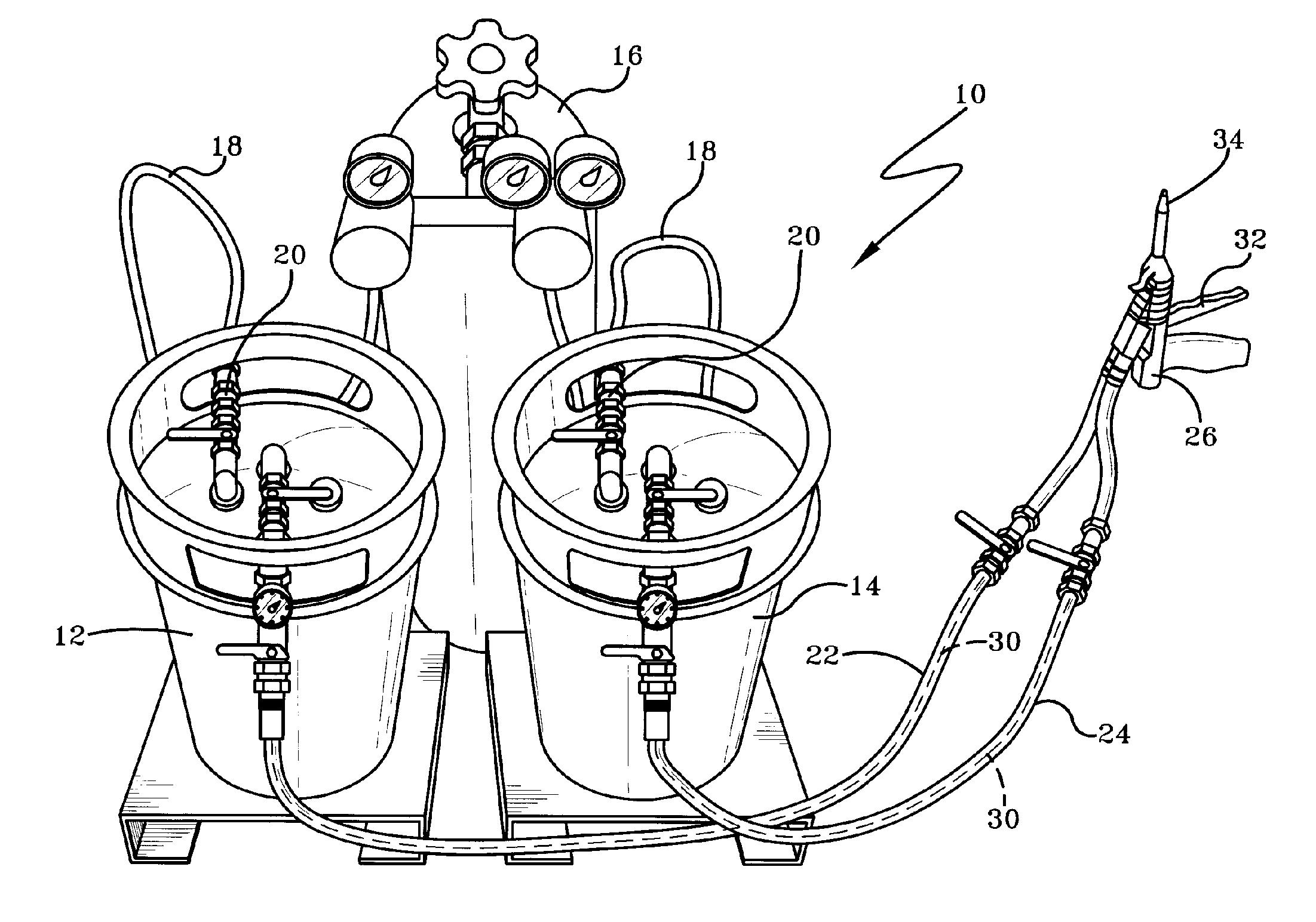
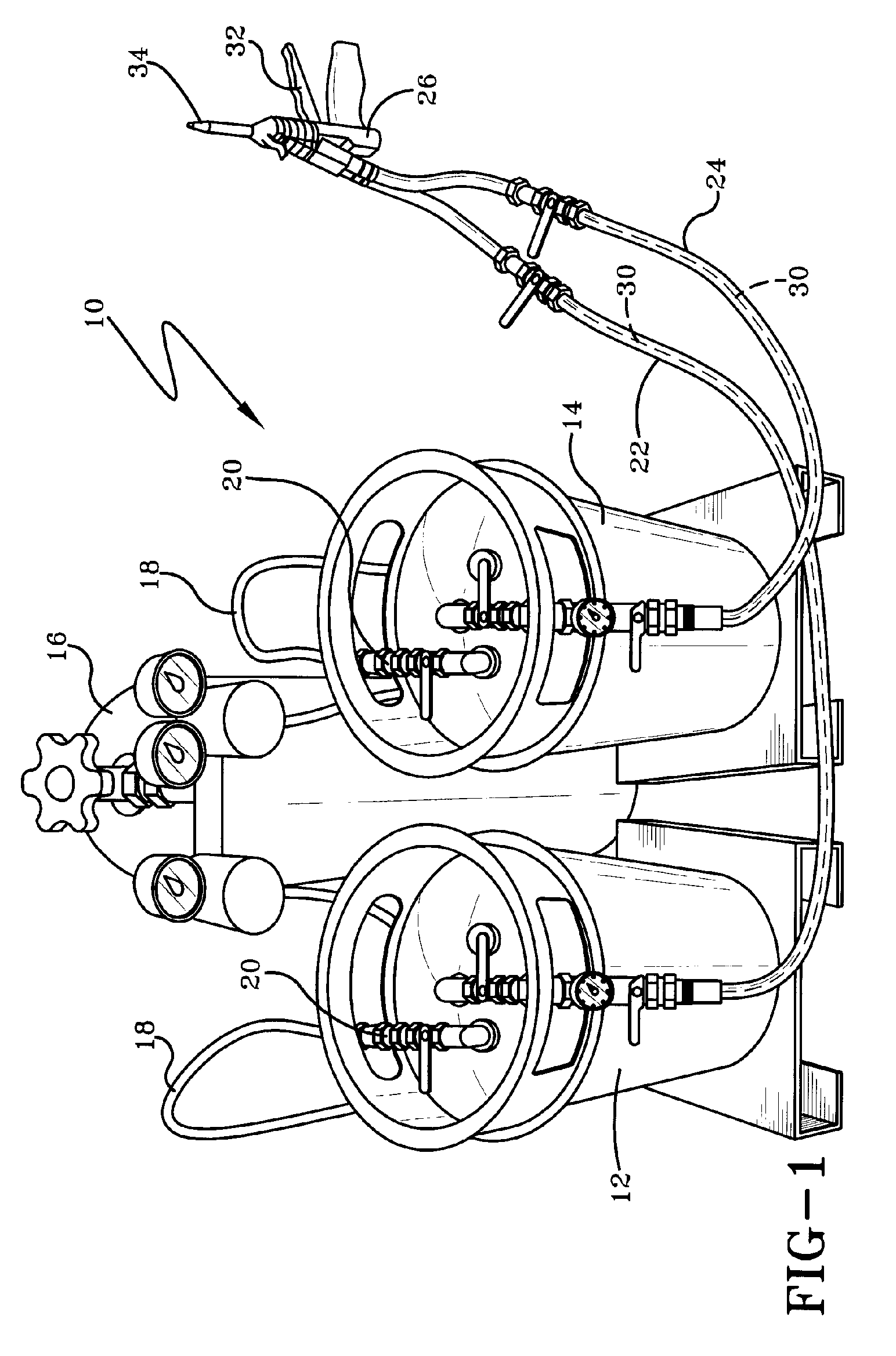
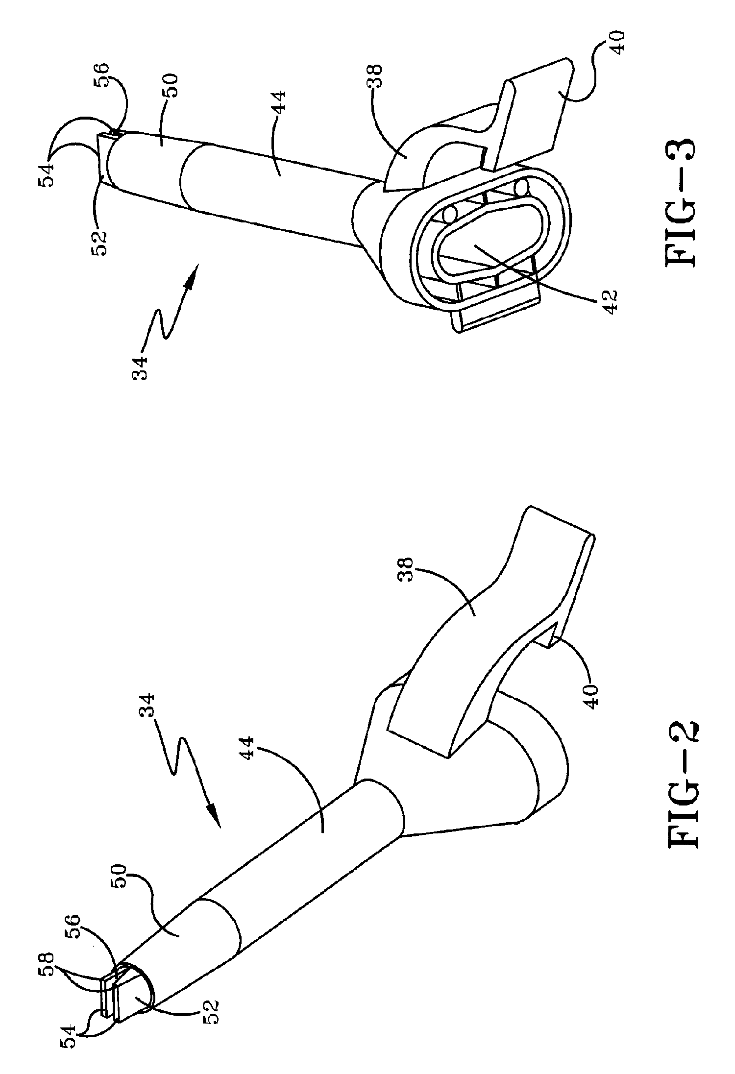
[0033] Referring now to the drawings wherein the showings are for purposes of illustrating the preferred embodiment of the invention only and not for purposes of limiting the same, the Figures show a preferred embodiment of the invention which provides for the rapid insulation of a desired surface using a two-component spray polyurethane froth foam system. Similar reference numbers refer to similar parts throughout the drawings.

[0034] A diagram of the equipment used in the invention described herein is shown in FIG. 1. Two tanks 12 and 14 separately store the chemical components (the “A” component and the “B” component) of the two-component polyurethane foam. The chemical storage tanks 12 and 14 are ideally the same size, as the chemicals within are combined at equal rates during use of the spray polyurethane foam insulation system 10. When the chemicals are not combined at equal rates, undesirable properties appear within the foam, such as incorrect consistency, incorrect color, u...


PUM

PropertyMeasurementUnit
pressureaaaaaaaaaa
angleaaaaaaaaaa
angleaaaaaaaaaa

Abstract

A process for cost-effectively and rapidly insulating a desired surface with spray foam insulation is described which includes the application of a polyurethane foam dispensed through heated conduits into a dispensing gun having a nozzle with essentially planar divergent lips having a triangular prism opening, the lips of the nozzle diverging at an angle of between about 5 and 35° inclusive, more preferably between 8 to 15° inclusive, most preferably 10 to 12° inclusive, thereby achieving application rates which are in excess of 70 Ft2 / min, and optimally in excess of 100 Ft2 / min.

Description

TECHNICAL FIELD [0001] This invention relates generally to a method of rapidly insulating a desired surface using a polyurethane froth foam for in-situ application of two-component polyurethane foam, and more specifically to a method of using a foam application gun with a two-component polyurethane foam insulation to rapidly insulate surfaces under all weather conditions including temperatures as low as 20° F. BACKGROUND OF THE INVENTION [0002] There are numerous applications in which spray polyurethane foam is used at a site for any number of applications in, but the most traditional use in the building trades is as a source of insulation. The Department of Energy reports that every year the average home wastes up to 40% of the energy used for heating and cooling as air moves through gaps, penetrations, and cracks in the exterior shell of the house, also known as the building envelope. Spray foam insulation is gaining in popularity because of its many benefits over conventional fib...

Claims


Application Information

Patent Timeline
Patent Type & Authority Applications(United States)
IPC IPC(8): F23D14/60
CPCB01F5/0619B01F2005/0631B01F2005/0637B29B7/325B29B7/7419B29B7/7447E04F21/12B05B9/04B05B7/0408B01F25/43161B01F25/4319B01F25/431972
Inventor DANSIZEN, RICHARD L.FISHBACK, THOMAS L.GANTENBEIN, STEFANHURRAY, PAULTAYLOR, ANTHONY J.
Owner ICP CONSTR INC
Why Eureka
Try Eureka