Aircraft capable of vertical and short take-off and landing

a technology of short take-off and landing and aircraft, applied in vertical landing/take-off aircraft, aircraft navigation control, gearing, etc., can solve the problems of insufficient performance, more widespread and successful use, and complex complex relationship between one or more horizontal driving and one or more vertical driving of vehicles

Active Publication Date: 2006-08-31
THE BOEING CO
View PDF60 Cites 82 Cited by
  • Summary
  • Abstract
  • Description
  • Claims
  • Application Information

AI Technical Summary

Benefits of technology

[0010] In still another aspect, the present invention includes a method for controlling aircraft flight including selectively adjusting fan blade pitch of a plurality of counter-rotating ducted wing fan sets mounted on a fuselage of the aircraft between about 0° and about 45° from a plane about which the wing fans rotate. The wing fan blade pitch adjustment is accomplished by actuating piezoelectric fibers embedded in a composite matrix that the wing fan blades are made of. The wing fan blade pitches are adjusted to control aircraft roll and vertical thrust. The method further includes selectively adjusting fan blade pitch of at least one counter-rotating ducted nose fan set mounted on the fuselage between about 0° and ab...

Problems solved by technology

Numerous disadvantages of conventional V/STOL vehicles have kept them from more widespread and successful use.
Many of these disadvantages stem from the fact that conventional designs are too complex and result in insufficient performance.
The complexities associated with having multiple power plants, one or more to drive the vehicle horizontally and one or more to drive the vehicle vertically, are pronounced.
The aforementioned augmented systems require even more structure, which adds weight and takes space.
Conventional V/STOL systems using the same power plant for horizontal and vertical thrust have challenges related to the complexity of their designs.
The additional structure required by these systems adds excessive complexity and unwanted weight to the aircrafts.
Whether using a single power plant or multiple power plants for horizontal and vertical propulsion, conventional V/STOL systems are frequently overly complex, too heavy, and inefficient.
In addition, there are many s...

Method used


Image

  • Aircraft capable of vertical and short take-off and landing
  • Aircraft capable of vertical and short take-off and landing
  • Aircraft capable of vertical and short take-off and landing

Examples


Embodiment Construction

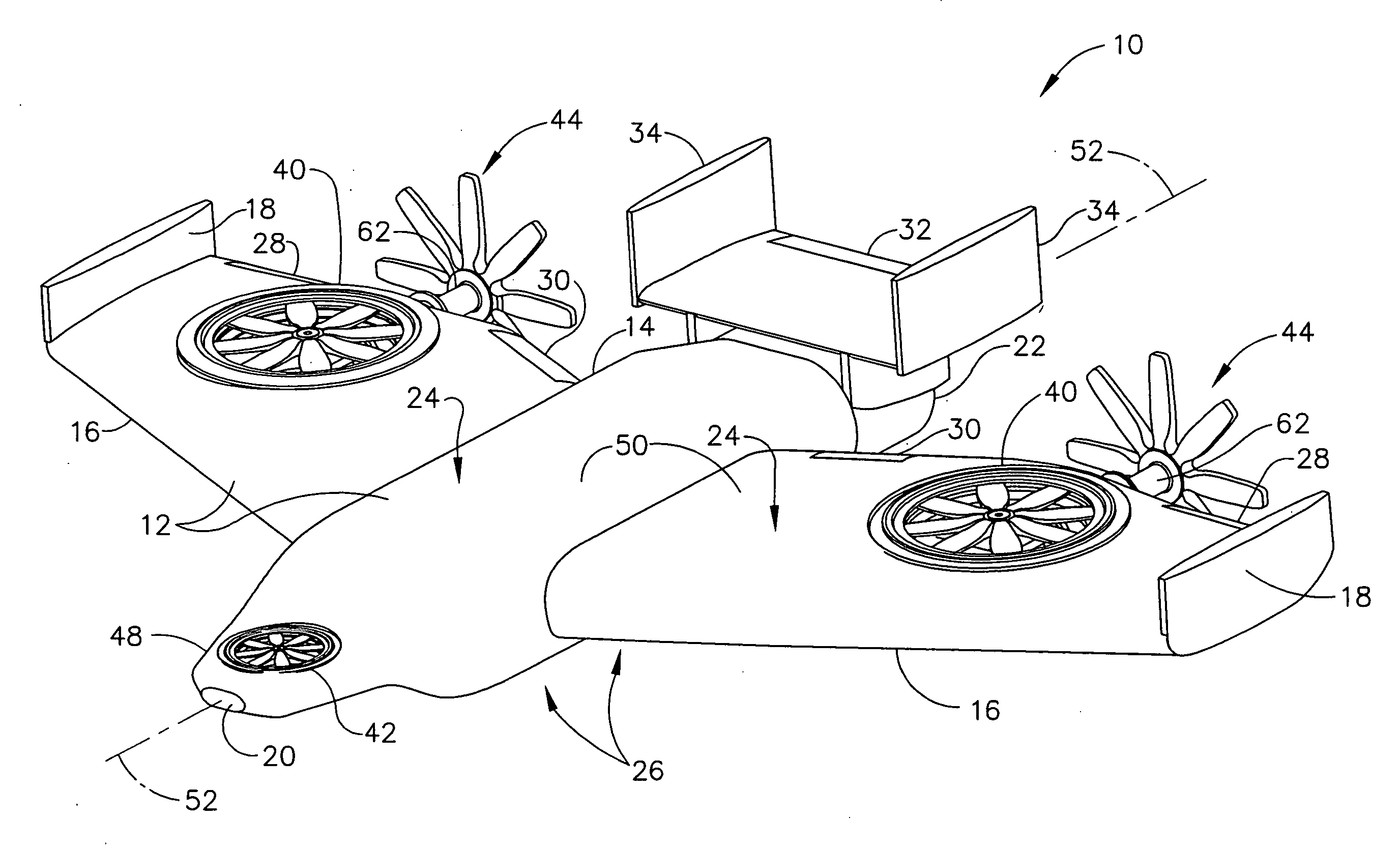
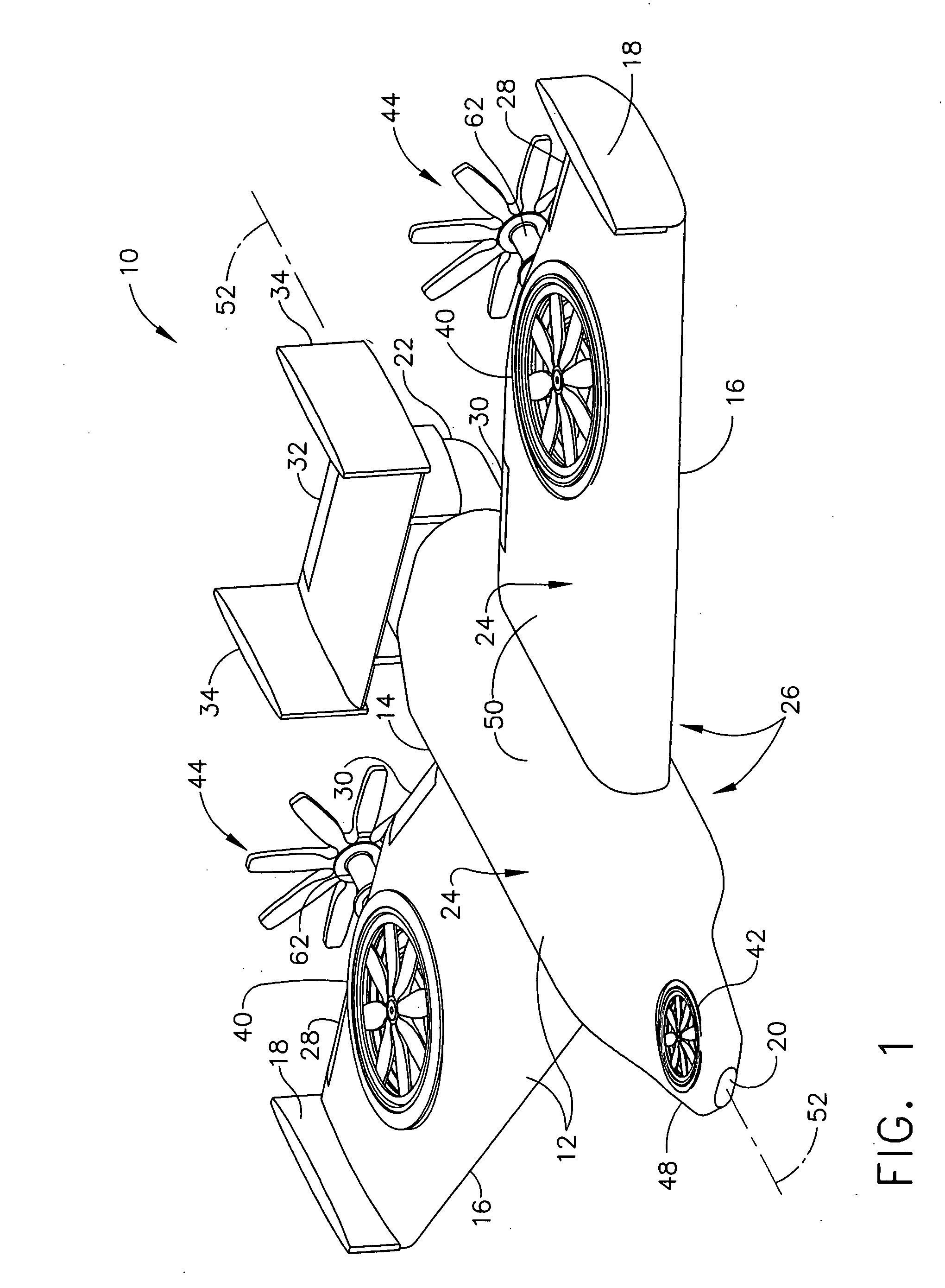
[0021] The present invention relates to aircraft, and more particularly to aircraft capable of vertical and short runway take-off and landing. Referring now to the figures, and more particularly to FIG. 1, aircraft according to a first embodiment of the present invention is designated in its entirety by reference number 10. The aircraft 10 has an airframe 12 including a fuselage 14 and at least two wings 16 extending laterally from the fuselage to wingtips 18 at their respective outer ends. The fuselage 14 extends between a forward end 20 and an aft end 22. Although the fuselage 14 may have other lengths without departing from the scope of the present invention, in one embodiment the fuselage has a length extending between the forward end 20 and the aft end 22 of between about 5 feet and about 40 feet. Although the aircraft 10 may have other wingspans without departing from the scope of the present invention, in one embodiment the aircraft has a wingspan extending between the wingti...


PUM


Abstract

Aircraft comprising an airframe having a forward end, an aft end opposite the forward end, a top extending between the forward end and the aft end, and a bottom opposite the top side. The aircraft further includes a power plant mounted on the airframe. In addition, the aircraft includes at least two propellers rotatably mounted on the airframe and powered by the power plant for moving the aircraft in a generally forward direction during operation of the propellers. Also, the aircraft includes at least two counter-rotatable fan sets mounted on the airframe and powered by the power plant for providing upward lift to the aircraft during operation of the fan sets.

Description

BACKGROUND OF THE INVENTION [0001] The present invention relates to aircraft capable of vertical take-off and landing and, more particularly, to aircraft capable of such maneuvers using split-torque face gear drives. [0002] Aircraft designed to allow vertical and short take-off and landing, hover, full forward, and transitional flight have existed since about the middle of the twentieth century. These vehicles are often referred to as dual mode or V / STOL aircraft because of their vertical and / or short take-off and landing capabilities. There are four primary types of V / STOL vehicles: those having a single power plant for horizontal and vertical thrust; those having separate power plants for horizontal and vertical thrust; combined systems having separate power plants for horizontal and vertical thrust and a supplemental power plant to assist vertical propulsion; and augmented systems having an auxiliary vertical propulsion device powered by the primary propulsion device(s). [0003] N...

Claims


Application Information

Patent Timeline
IPC IPC(8): B64C29/00
CPCB64C15/14B64C29/0025B64D35/04F16H1/222F16H1/20F16H1/203F16H1/206F16H3/02
Inventor HEATH, GREGORY F.GILBERT, RONALD E.HANSEN, TERRELL W.SLAUGHTER, STEPHEN C.
Owner THE BOEING CO
Why Eureka
Try Eureka