Watch

Active Publication Date: 2006-08-31
SEIKO INSTR INC
View PDF3 Cites 2 Cited by
  • Summary
  • Abstract
  • Description
  • Claims
  • Application Information

AI Technical Summary

Benefits of technology

[0014] In the present invention, the front-end portion of the mounting screw threaded into the threaded hole in the barrel is engaged in the engaging recessed portion of the stem pipe inserted in the pipe mounting hole in the barrel. The stem pipe is held to the barrel to prevent its movement in the axial direction. This holding is not impaired by manipulation of the crown. Therefore, there is no danger that the waterproofness provided between the barrel and the stem pipe by the waterproof packing sandwiched between the barrel and the stem pipe along a radial direction of the stem pipe not in the direction in which the center axis of the stem pipe extends is impaired by manipulations of the crown. The holding of the stem pipe to the barrel is released by disengaging the mounting screw from the engaging recessed portion, which is done by moving rearwardly the screw that can be moved forward and rearward from outside the barrel. Consequently, the stem pipe can be pulled out from the barrel. Therefore, the threadedly locking function can be exhibited by the engagement between the external thread of the barrel outside protruding portion and the internal thread of the crown. Where the threadedly locking function deteriorates as the crown is rotationally manipulated by releasing the threaded engagement to release the threadedly locking function, the stem pipe or the like can be replaced for the barrel.
[0015] In a preferred embodiment of the present invention, the engaging recessed portion is formed as an annular groove extending continuously

Problems solved by technology

In the watch equipped with the threadedly locking structure, as the crown is repeatedly rotationally manipulated, the internal thread of the crown and the external thread of the stem pipe which are threaded together may wear down or scrape off each other.
Consequently, the function of the threadedly locking deteriorates.
Even in this structure, however, a rotati

Method used


Image

  • Watch
  • Watch
  • Watch

Examples


Example

[0026] A first embodiment of the present invention is described by referring to FIGS. 1-3.

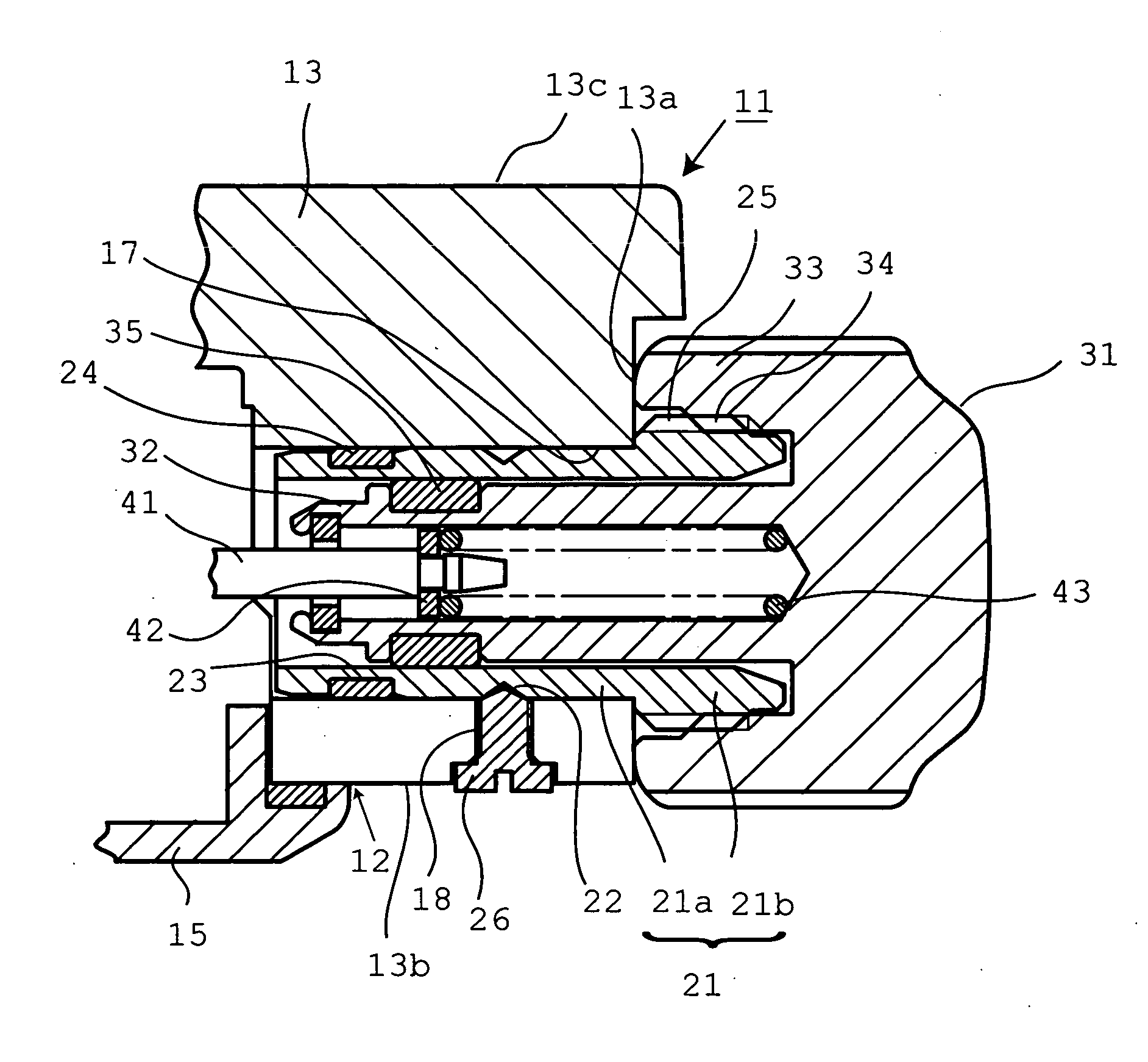
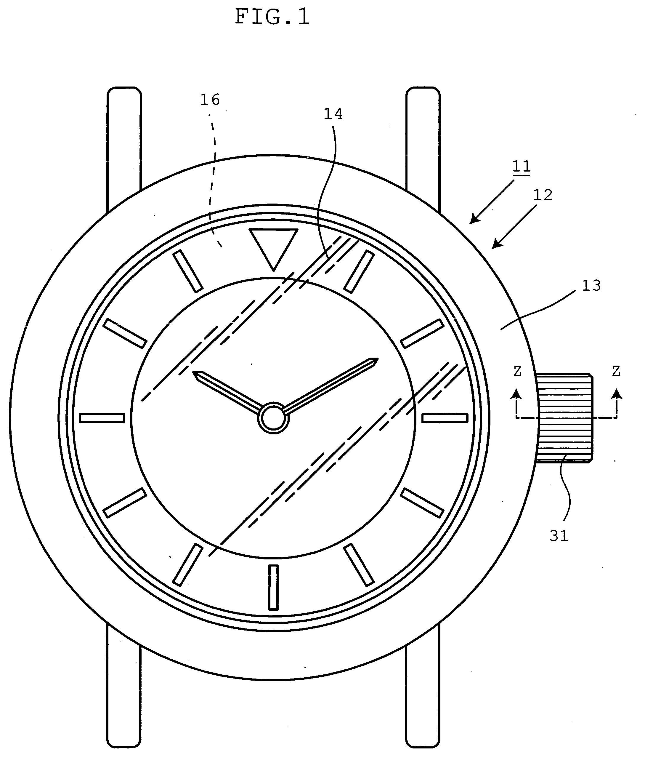
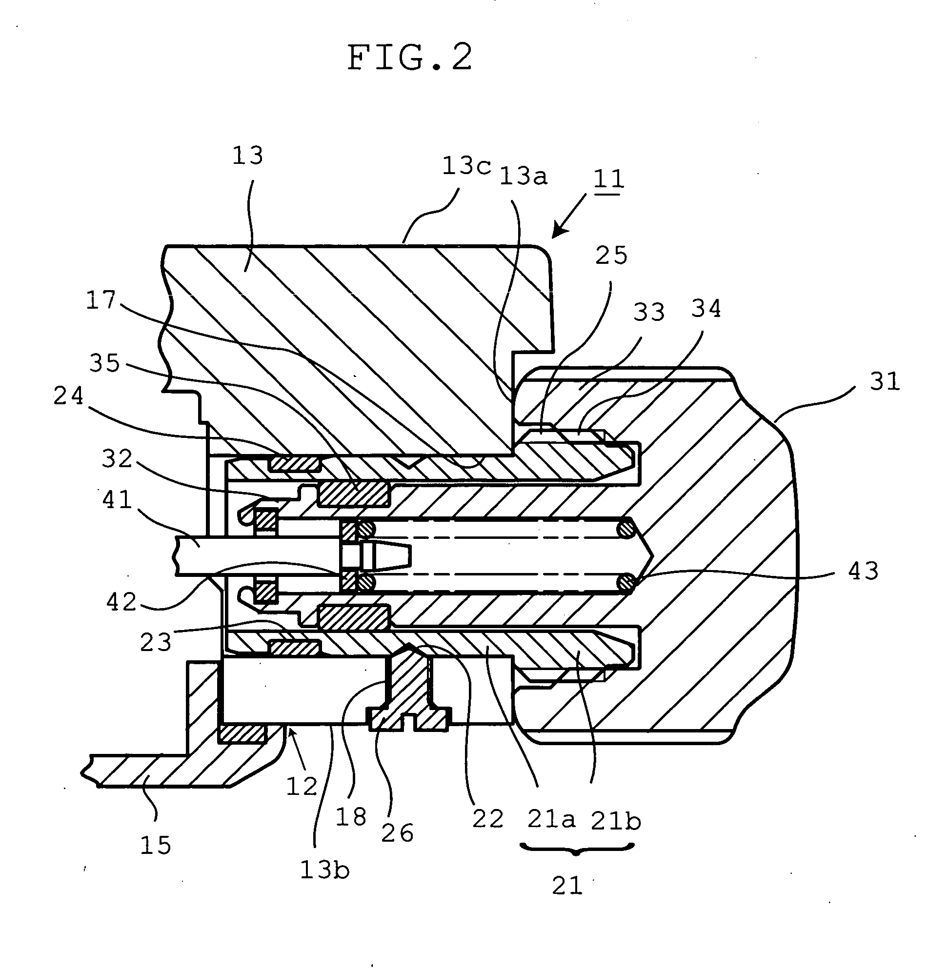
[0027] In FIG. 1, symbol 11 indicates a watch equipped with a function of threadedly locking the crown such as a wristwatch. The wristwatch 11 incorporates a watch movement (not shown) or the like in a watch outer assembly 12. The watch movement may be any one of a movement powered by a small-sized battery or spring, an automatically wound movement, a movement corresponding to a digital watch that digitally displays the time and so forth on a dial by a quartz oscillation module, a movement corresponding to a digital watch, and a combination with others.

[0028] The watch outer assembly 12 has an annular barrel 13 made of a metal such as stainless steel or titanium or synthetic resin. A cover glass 14 is mounted to the whole surface of the barrel in the direction of thickness in a liquid tight manner. A rear cover 15 (see FIG. 2) made of a metal or the like is mounted to the rear surface of the ...

Example

[0052]FIGS. 4 and 5 show a second embodiment of the present invention. Since the second embodiment is essentially identical with the first embodiment, those portions of the second embodiment which are identical or similar in structure or function with the corresponding portions of the first embodiment are indicated by the same symbols as in the first embodiment and their description is omitted. The points which are different from the first embodiment are described in the following.

[0053] In the second embodiment, the engaging recessed portion 22 in the outer surface of the insertion portion 21a is formed by a small hole as shown in FIG. 5 instead of an annular groove. This small hole (engaging recessed portion 22) is formed by pushing a drill against the insertion portion from a direction perpendicular to the center axis of the insertion portion 21a. The cross section of the hole assumes a V-shaped form as shown in FIG. 4. Furthermore, in this embodiment, alignment marks are prefer...

Example

[0055]FIGS. 6 and 7 show a third embodiment of the present invention. Since the third embodiment is essentially identical with the first embodiment, those portions of the third embodiment which are identical or similar in structure or function with the corresponding portions of the first embodiment are indicated by the same symbols as in the first embodiment and their description is omitted. The points which are different from the first embodiment are described in the following.

[0056] In the third embodiment, the engaging recessed portion 22 in the outer surface of the insertion portion 21a is formed by a cutout-like groove formed by removing a part of the outer surface of the insertion portion 21a as shown in FIG. 7, instead of an annular groove. This engaging recessed portion 22 has a flat bottom surface 22a. This engaging recessed portion 22 has been machined by passing a milling cutter through the outer surface of the insertion portion 21a from a direction perpendicular to the ...


PUM


Abstract

A watch is offered in which there is no danger that the waterproofness is impaired by manipulation of the crown. The watch permits replacements of parts around the crown in a case where the threadedly locking function has deteriorated. The watch is based on a watch in which the crown is threadedly locked to a stem pipe mounted to a barrel. The barrel is provided with a pipe installation hole and with a threaded hole rectangularly in communication with this installation hole. The stem pipe has an insertion portion and a barrel outside protruding portion. The insertion portion is inserted in the pipe installation hole such that the insertion portion can be withdrawn from outside the barrel. The barrel outside protruding portion is disposed outside the barrel and has an external thread to which the crown is removably threaded. An engaging recessed portion is formed in the outer surface of the insertion portion. Annular waterproof packing is sandwiched between the pipe installation hole and the insertion portion. A mounting screw is threaded into the threaded hole so as to be movable back and forth. A front-end portion of this screw is inserted in the engaging recessed portion, and the stem pipe is held to the barrel.

Description

BACKGROUND OF THE INVENTION [0001] 1. Field of the Invention [0002] The present invention relates to a watch equipped with a structure for holding the crown to prevent it from being inadvertently rotated. [0003] 2. Description of the Prior Art [0004] In some of watches such as wristwatches, the crown is locked by making use of threaded engagement to prevent inadvertent rotation of the crown during carriage (the structure or function is referred to as threadedly locking, threadedly locking structure, or threadedly locking function in the present specification). [0005] In the threadedly locking structure, a stem pipe is mounted to a barrel in which a watch movement is incorporated. The internal thread of the crown which is fitted over a barrel outside protruding portion is threadedly engaged to an external thread formed on the outer surface of the barrel outside protruding portion of this pipe. In this way, during normal times, the crown is threadedly engaged to the outer surface of t...

Claims


Application Information

Patent Timeline
IPC IPC(8): G04B27/00
CPCG04B3/043G04B37/103G04B3/041
Inventor OMORI, NOBUKAZUHIRANUMA, HARUKI
Owner SEIKO INSTR INC
Why Eureka
Try Eureka