Eureka AIR delivers breakthrough ideas for toughest innovation challenges, trusted by R&D personnel around the world.

Diaphragm and speaker

Inactive Publication Date: 2006-08-31
PIONEER CORP +1
View PDF6 Cites 6 Cited by
  • Summary
  • Abstract
  • Description
  • Claims
  • Application Information

AI Technical Summary

Benefits of technology

[0011] A diaphragm according to an aspect of the present invention includes: a vibrating member having a substantially thin-plate shape; and a substantially filmy base material that is arranged on a surface of the v

Problems solved by technology

The difference of the tensile strengths generates deformation of the diaphragm such as bending that causes degradation of sound quality, which might cause music or the like to be output with sound quality different from the original one.

Method used


Image

  • Diaphragm and speaker
  • Diaphragm and speaker
  • Diaphragm and speaker

Examples


Embodiment Construction

)

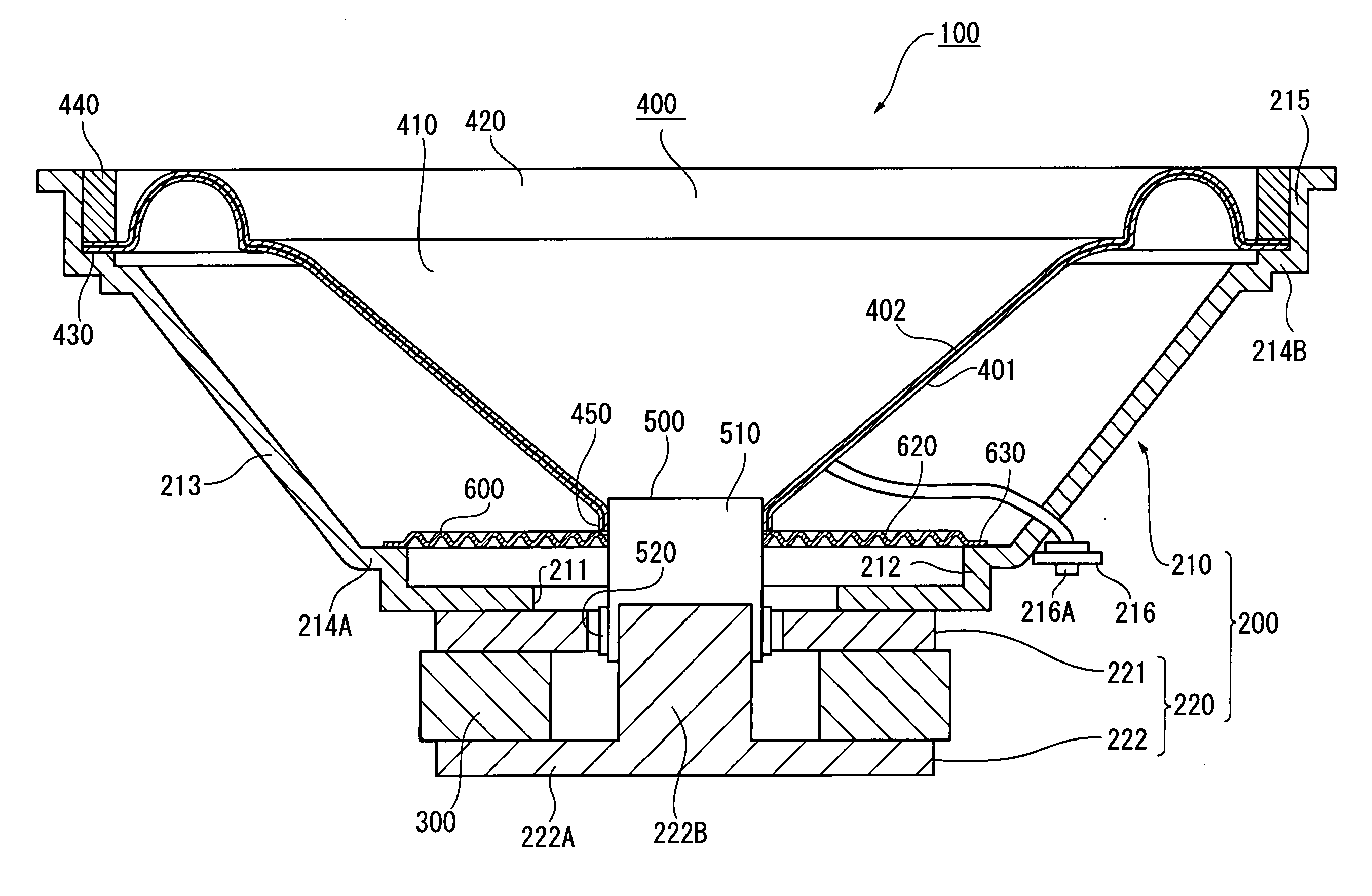
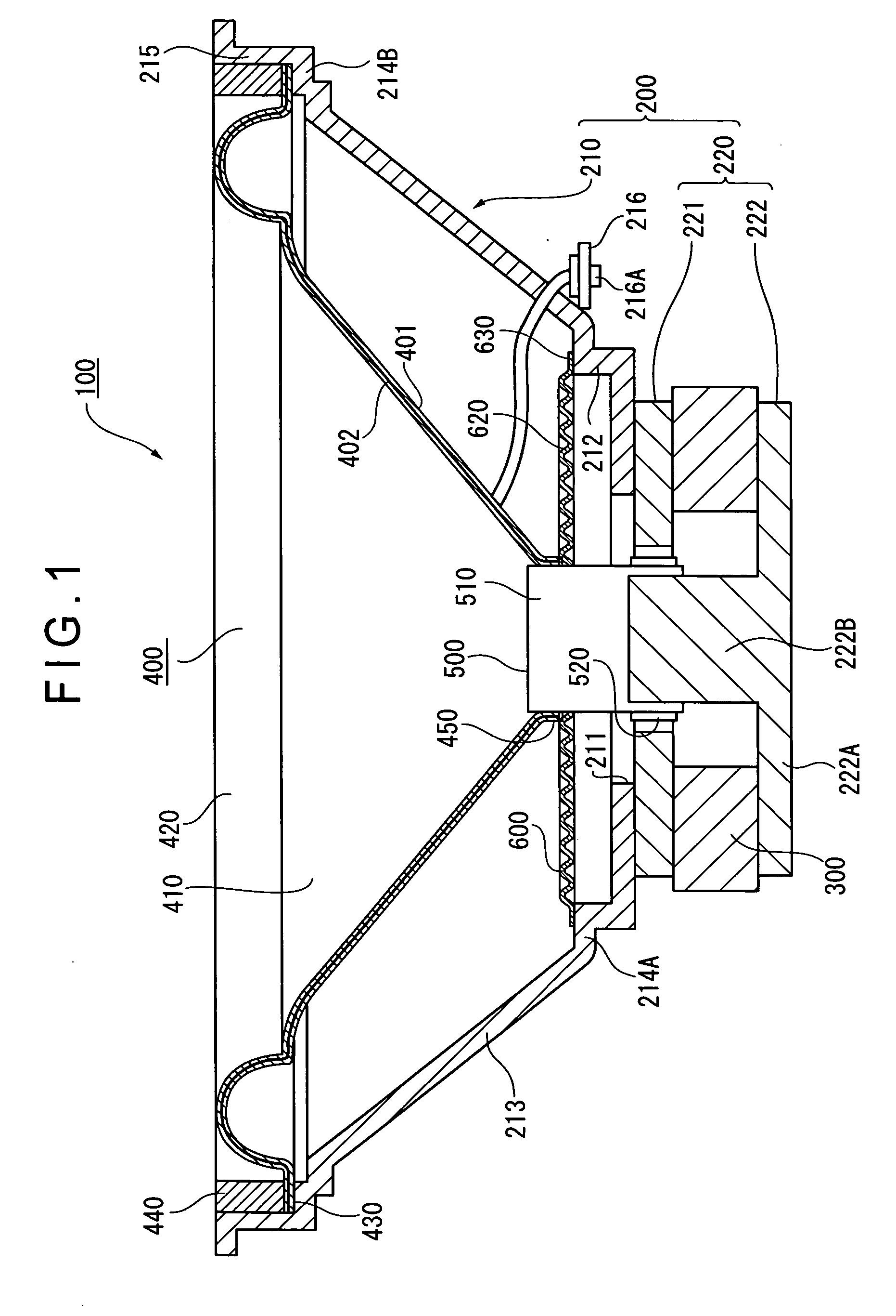
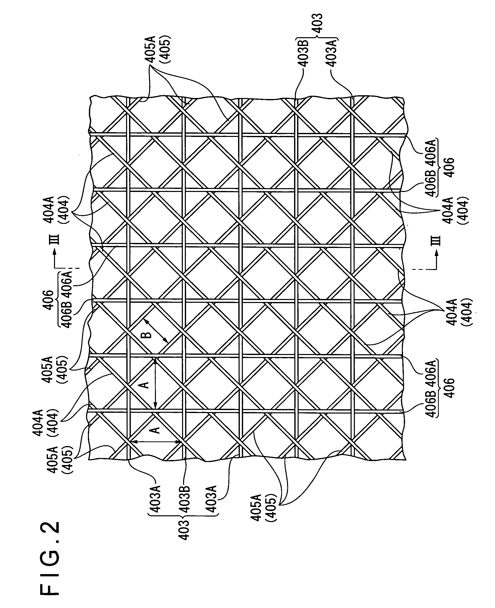
[0022] An embodiment of a speaker of the present invention will be described below with reference to the attached drawings. Note that although a cone speaker is exemplified in the present embodiment, the speaker is not limited thereto. FIG. 1 is a cross section briefly showing an arrangement of the speaker according to the embodiment of the present invention. FIG. 2 is a plan view showing a weaving structure of a base material. FIG. 3 is a cross section taken along a line III-III of the weaving structure of the base material in FIG. 2.

[Arrangement of Speaker]

[0023] In FIG. 1, the reference numeral 100 denotes a speaker, and the speaker 100 outputs audio data by sound, the audio data being an electrical signal transmitted from an electrically-connected reproducing device The speaker 100 includes a body 200, a magnet (magnetic material) 300, a diaphragm 400, a voice coil bobbin 500 and a protector (not shown).

[0024] A frame 210 of the body 200 is made of a hard synthetic resin, a ...


PUM


Abstract

A diaphragm (400) of a speaker (100) includes a vibrating member having a substantially thin-plate shape and a base material disposed substantially at the center in a width direction of the vibrating member. The base material is formed by a woof group, a front diagonal thread group, a back diagonal thread group and a warp group, the groups being arranged so as to cross with each other and have axial directions different from each other. Accordingly, tensile strengths of the diaphragm (400) in the axial directions of the groups, i.e., tensile strengths in four directions, can be set to substantially the same. Accordingly, since the number of directions having substantially the same tensile strength is larger than conventional arrangements using triaxial fabrics, occurrence of deformation such as bending of the diaphragm (400) due to resonance can be prevented as compared to the conventional arrangements. Therefore, the speaker (100) capable of vibrating properly can be provided.

Description

BACKGROUND OF THE INVENTION [0001] 1. Field of the Invention [0002] The present invention relates to a diaphragm using a substantially filmy base material that is formed by a plurality of linear members and a speaker. [0003] 2. Description of Related Art [0004] There has been conventionally known a diaphragm used for a speaker or the like, which employs a so-called triaxial fabric woven by a first, second and third linear members that cross with each other at, for instance, an angle of about 60° (see, for instance, Document 1: Japanese Patent Publication No. 2681991, left column of page 2 to right column of page 3, Document 2: JP-A-2002-78077, right column of page 3, Document 3: JP-A-8-47083, right column of page 2, and Document 4: JP-A-5-284594, right column of page 2). [0005] Document 1 discloses an arrangement in which a prepreg prepared by impregnating a triaxial fabric with a thermosetting resin is placed on a cavity plate having a desired shape. Then, a core is placed on the p...

Claims


Application Information

Patent Timeline
IPC IPC(8): H04R11/02
CPCH04R7/10H04R7/125H04R9/06H04R31/003H04R2307/021H04R2307/023H04R2307/025H04R2307/029D03D13/002
Inventor HACHIYA, SATOSHIMATSUMOTO, KOJIOGAHARA, MICHIHIRO
Owner PIONEER CORP
Why Eureka
Eureka Blog
Learn More