
Galvanic cell

Active Publication Date: 2006-08-31
LITRONIK BATTERIETECHNOLOGIE GMBH
View PDF8 Cites 25 Cited by
  • Summary
  • Abstract
  • Description
  • Claims
  • Application Information

AI Technical Summary

Benefits of technology

[0017] Simultaneously, the mounting of the battery is made easier and the functional reliability of the battery is increased, in that the electrodes may be positioned and fixed by the molded part. The molded part simultaneously allows secure contacting of the electrodes via their contact tabs, which are each individually held securely in a separate slot by the molded part.

Problems solved by technology

Special implants of this type place high demands on a battery, since the power supply of the implant is typically only provided by the battery.
If the battery is exhausted or also in case of a technical problem with the battery, the entire implant must typically be replaced.

Method used


Image

  • Galvanic cell
  • Galvanic cell
  • Galvanic cell

Examples


Embodiment Construction

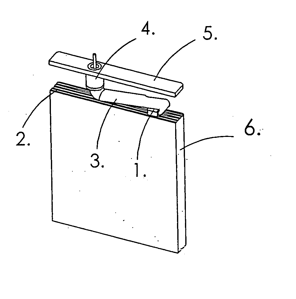
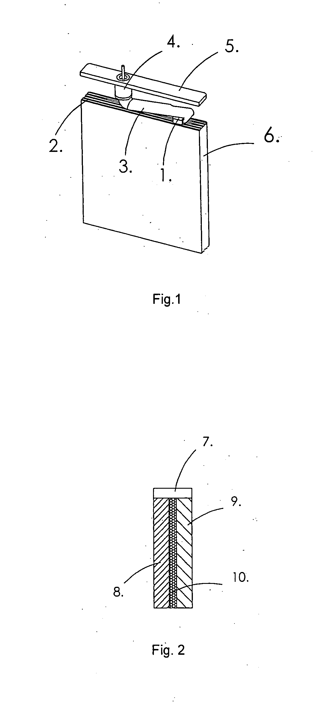
[0029]FIG. 1 shows a battery according to the related art. The battery has a housing having a vessel-like housing part 6 and a closure part 5, through which a bushing 4 is guided. When the battery is completely assembled, the vessel-like housing part 6, the closure part 5, and the bushing 4 are connected to one another so tightly that the battery is hermetically sealed. Electrodes 2 are positioned in the interior of the housing, which are provided with contact tabs 1. The contact tabs 1 of the electrodes 2 are combined and electrically connected to a contact in the form of a bent metal pin 3 of the bushing 4, which is implemented as a glass-metal bushing, preferably through welding. When the closure part 5 is closed, the bent pin 3 is pressed down on the electrodes 2 combined into a packet and fixed in this position by welding the closure part 5 to the housing part 6 like a hollow vessel.

[0030]FIG. 2 shows the schematic construction of a battery according to the present invention. ...


PUM


Abstract

A battery having a housing assembled from multiple parts, of which one housing part is implemented like a vessel having an initially open front side and the other housing part is a closure part, which closes the vessel-like housing part on its initially open front side, and having at least one first and at least one second electrode, each of which is formed by a planar material, of which the first electrode is electrically connected to an electrically conductive housing part of the battery, while the second electrode is electrically connected to an electrically conductive contact, which is electrically insulated from the remaining housing, the battery comprising a molded part which is provided with at least one first recess for receiving and positioning at least one section of the first electrode or the first electrodes at a time.

Description

BACKGROUND OF THE INVENTION [0001] The present invention relates to a galvanic cell, also referred to as a battery in the following, which is particularly suitable for use in electromedical implants such as pacemakers, defibrillators and the like. [0002] Special implants of this type place high demands on a battery, since the power supply of the implant is typically only provided by the battery. If the battery is exhausted or also in case of a technical problem with the battery, the entire implant must typically be replaced. This typically requires surgery and a hospital stay. Therefore, high demands are placed both on the energy density of the galvanic cell and also on its reliability. [0003] Typically, hermetically sealed galvanic cells of high energy and power density are used as batteries for implants such as pacemakers or defibrillators. Galvanic cells of this type are especially suitable for use in implantable medical devices. Corresponding batteries are, for example, describe...

Claims


Application Information

Patent Timeline
IPC IPC(8): H01M4/50H01M50/54
CPCH01M10/04H01M10/0413H01M2/065H01M2/266H01M6/00Y02E60/10H01M50/186H01M50/191H01M50/54Y02P70/50
Inventor DREWS, JUERGENHICKMANN, STEFFENSTAUB, ROLAND
Owner LITRONIK BATTERIETECHNOLOGIE GMBH
Learn More