Spring clip and method for assembling same

a spring clip and spring technology, applied in the field of surgical spring clips, can solve the problems of high assembly cost, unsuitable for peripheral vascular surgery, unsuitable for use in access devices such as trocars and endoscopes, etc., and achieve the effects of reducing trauma, facilitating engagement, and specific strength and tension properties

Active Publication Date: 2006-08-31
APPL MEDICAL RESOURCES CORP
View PDF12 Cites 181 Cited by
  • Summary
  • Abstract
  • Description
  • Claims
  • Application Information

AI Technical Summary

Benefits of technology

[0007] The tension spring comprises one or more turns and the finger tabs may include cavities or grooves to facilitate engagement with the fingers of a user or the jaws of a clip applier. That is, the spring clip may be manually actuated or remotely actuated using a clip applier. It is appreciated that the spring clip may be of any size and shape in accordance with the needs and requirements of each surgical procedure. It is further appreciated that the tension spring may be made of different wire materials, wire diameters, wire cross-section

Problems solved by technology

As a result, this configuration of the surgical clips of the prior art has made them particularly unsuited for use in peripheral vascular surge

Method used


Image

  • Spring clip and method for assembling same
  • Spring clip and method for assembling same
  • Spring clip and method for assembling same

Examples


Embodiment Construction

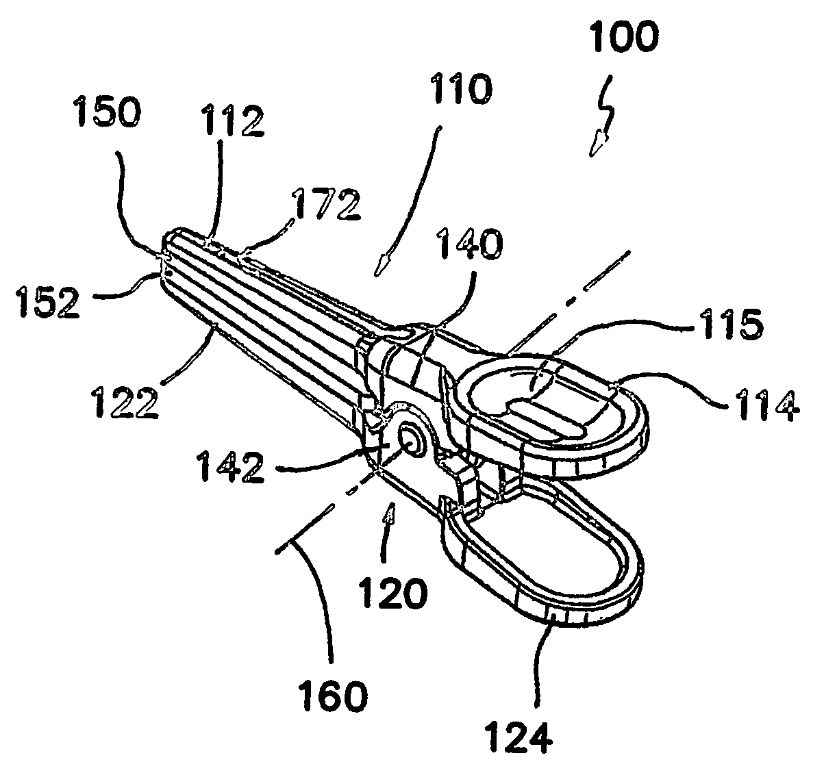
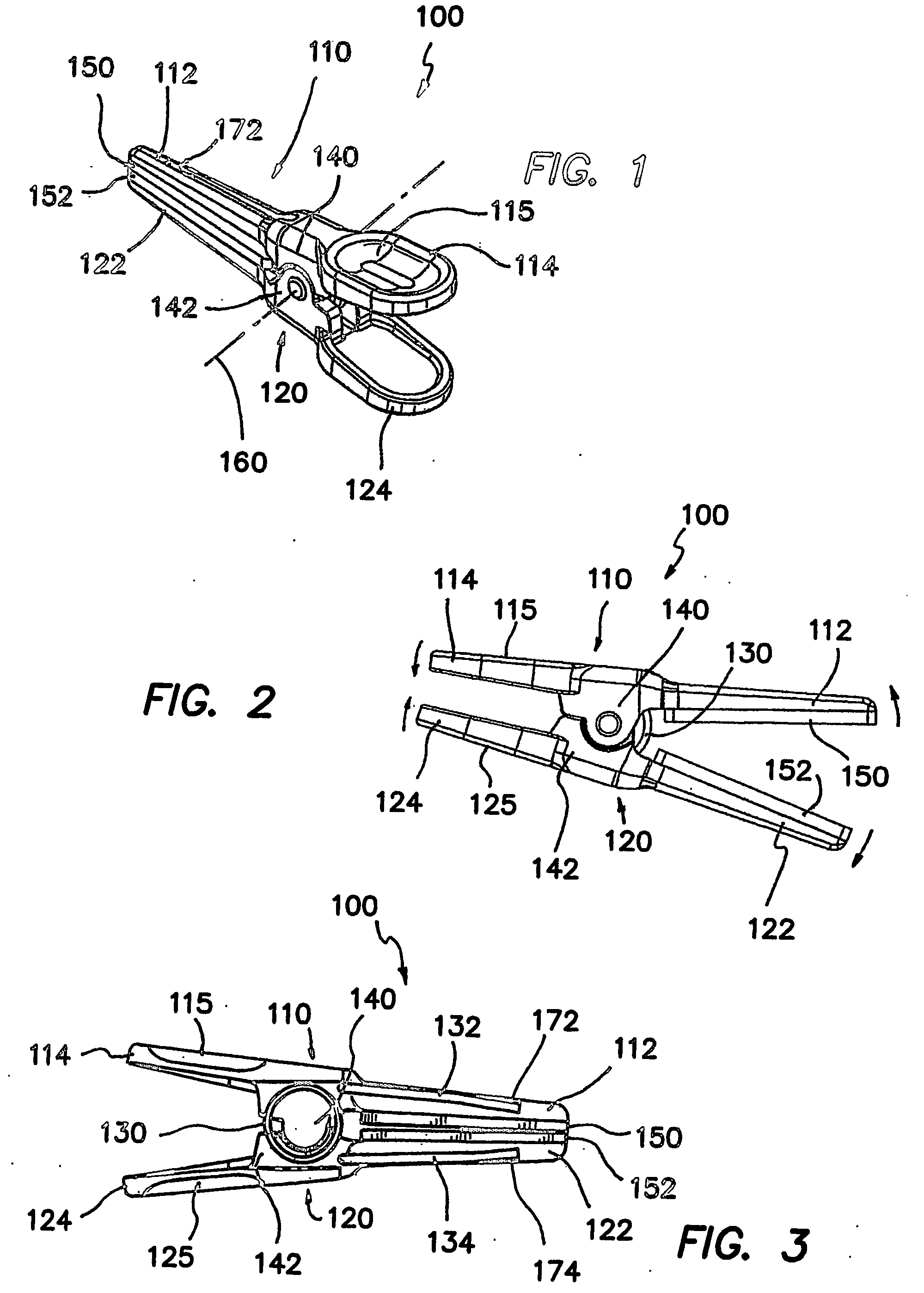
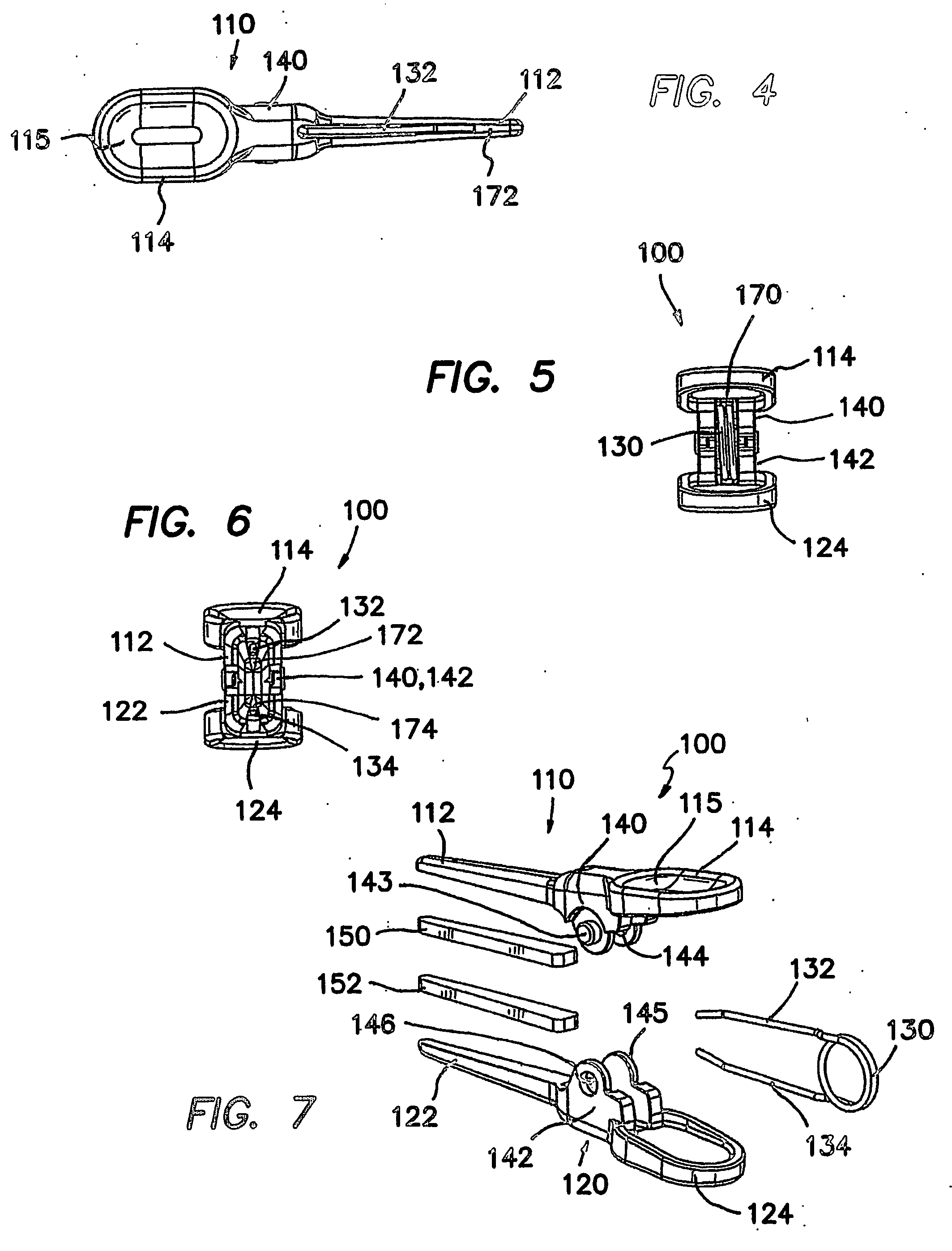
[0027]FIGS. 1-6 illustrate a jaw spring clip 100 in accordance with the first embodiment of the present invention. The spring clip 100 includes a first molded portion 110 having a first jaw 112 and a first finger tab 114, a second molded portion 120 coupled to the first molded portion 110 and having a second jaw 122 and a second finger tab 124, and a tension spring 130 coupled to both the first and second molded portions 110, 120 to hold the clip assembly together. The first and second molded portions 110, 120 may be molded into any low profile and / or narrow width configuration to suit a user's need. In addition, the first and second molded portions 110, 120 may be identical components. The first and second jaws 112, 122 are relatively movable between a first relatively proximate position as illustrated in FIG. 3 and a second relatively spaced position as illustrated in FIG. 2. The first and second molded portions 110, 120 are moveable by operation of the first and second finger tab...


PUM


Abstract

A surgical clip assembly is provided having two molded components and a tension spring. In one aspect of the invention, the spring clip includes a first molded portion having a first jaw and a first finger tab, a second molded portion coupled to the first molded portion and having a second jaw and a second finger tab, and a tension spring coupled to both the first and second molded portions. The first and second molded portions may be identical components and are moveable by operation of the first and second finger tabs between a generally closed position and a generally open position. The finger tabs may include cavities or grooves to facilitate engagement with a user or the jaws of a clip applier. The jaws may be shaped, curved or bent to provide access to specific areas of a procedure. Each of the jaws can be provided with an insert to further reduce trauma and increase traction with a target body conduit In a preferred process of assembling the clip, the tension spring is wound at least one turn forming a central coil and two extensions, and each of the molded portions is formed with a hinge area. Each of the hinge areas includes a hinge stud and a hinge cavity. The hinge areas operate to align and snap-fit with one another to form the clip assembly. With the assembly process of the invention, the extensions of the tension spring may be mounted into guide slots or ribs of either the jaws or finger tabs of the molded portions. A feature of the present invention is different tension springs having various strength and tension properties may be used in accordance with the needs and requirements of each surgical procedure without changing the construction of the molded portions.

Description

[0001] This is a non-provisional application claiming the priority of provisional application Ser. No. 60 / 452,574 filed Mar. 6, 2003, entitled “Spring Clip and Method for Assembling Same”, which is fully incorporated herein by references.BACKGROUND OF THE INVENTION [0002] 1. Field of the Invention [0003] This invention generally relates to surgical clips and clamps and, more specifically, to an improved surgical spring clip and an improved method for assembling such a clip. [0004] 2. Discussion of the Prior Art [0005] Clips and clamps are commonly used in surgical procedures to interrupt or inhibit fluid flow in various body tissues and / or conduits such as arteries, veins and ducts. These clips have been formed with generally rigid parallel jaws, each of which is attached to a respective barrel portion. The barrel portions have been telescopically movable relative to each other to house a compression spring. Finger tabs have been attached to the barrel portions generally at their ou...

Claims


Application Information

Patent Timeline
IPC IPC(8): A61B17/08A61BA61B17/122
CPCA61B17/083A61B17/122A61B17/1227
Inventor SAKAKINE, GHASSANGADBERRY, DONALD L.
Owner APPL MEDICAL RESOURCES CORP
Why Eureka
Try Eureka