Partition wall

a technology of partition wall and wall element, applied in the field of partition wall, can solve the problems of inability to change the embodiment of unalterable embodiment, inability to use variablely, and only in a limited extent, and achieve the effect of wide-ranging flexibility and variability of the partition wall, and enhanced sound absorption property of the wall elemen

Inactive Publication Date: 2006-09-07
KRAFT PETER
View PDF25 Cites 1 Cited by
  • Summary
  • Abstract
  • Description
  • Claims
  • Application Information

AI Technical Summary

Benefits of technology

[0018] The insertable wall panels can be produced from different materials. Thus, the wall panels can be produced in particular from wood, metal, or plastic. In addition, it is conceivable that the wall panels are coated or veneered with a flat material, e. g. with cloth or plastic, or covered with cloth. In particular by covering with cloth the sound-absorbing property of the wall element can be enhanced quite significantly. Furthermore, an optimal adaptation to the other furniture can be accomplished by covering with cloth, where it is possible that not the wall panel itself but rather the frame is covered immediately before the wall panel. Wide-ranging flexibility and variability of the partition wall is also realized thereby.

Problems solved by technology

The generic partition wall is, however, problematic in practice to the extent that a specific appearance is defined in advance when procuring the partition wall, which due to the concrete, unalterable embodiment cannot be changed, or can only be changed to a limited extent.
Variable use is thus not possible, or is possible only within narrow limits.

Method used


Image

  • Partition wall
  • Partition wall
  • Partition wall

Examples


Embodiment Construction

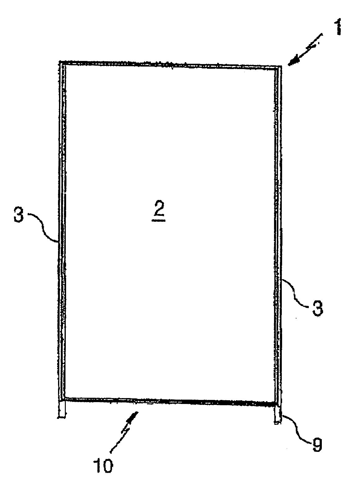
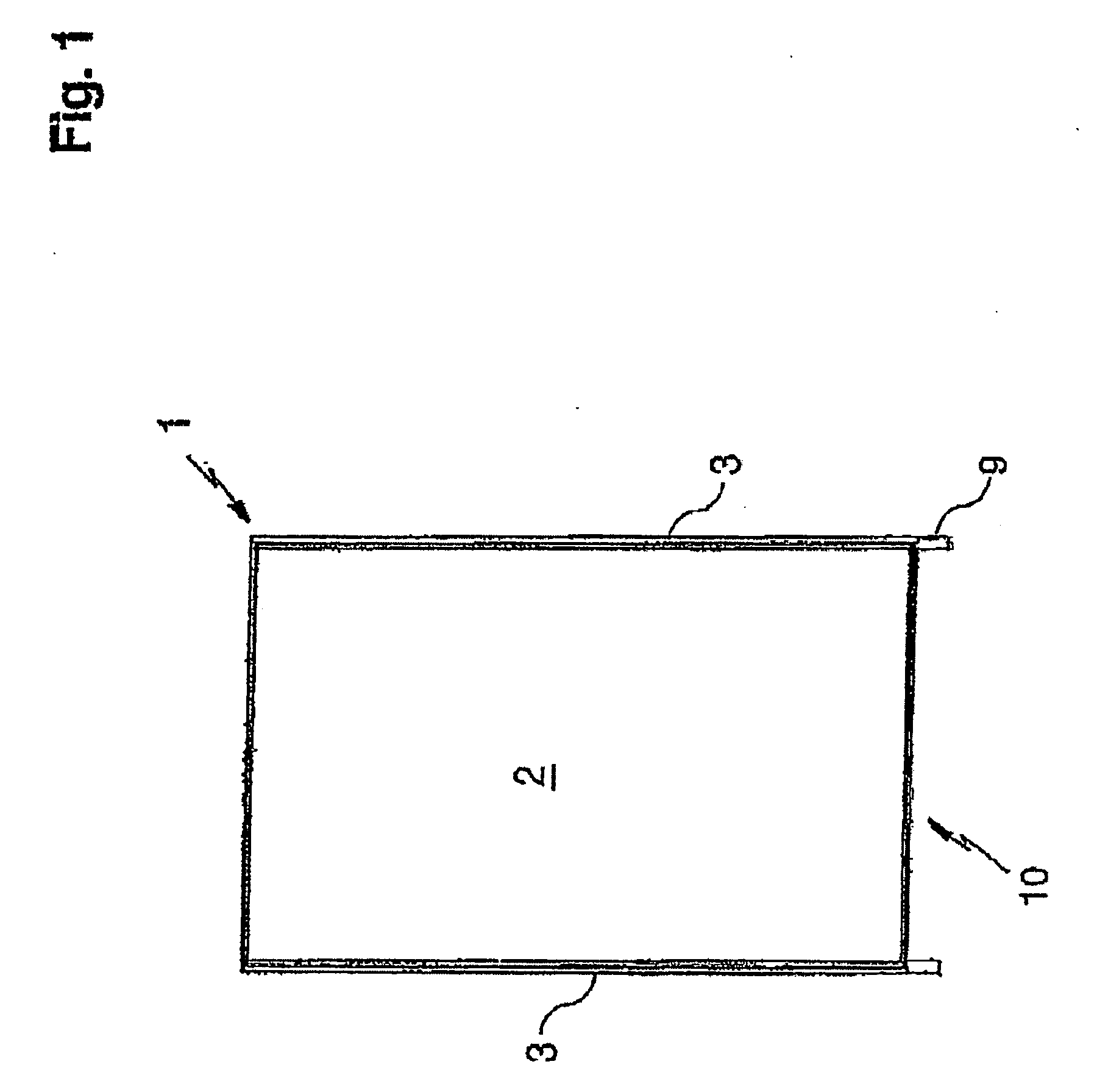
[0029]FIG. 1 shows a partition wall according to the invention in the form of a single wall element 1, it being understood that several wall elements 1 can be connected to one another to form the partition wall. The wall element 1 comprises a wall panel 2 and frame parts enclosing the wall panel 2 to form a frame 3.

[0030] According to the invention, on at least on one side of the wall element 1 the wall panel 2 can be inserted into the frame 3 and correspondingly exchanged.

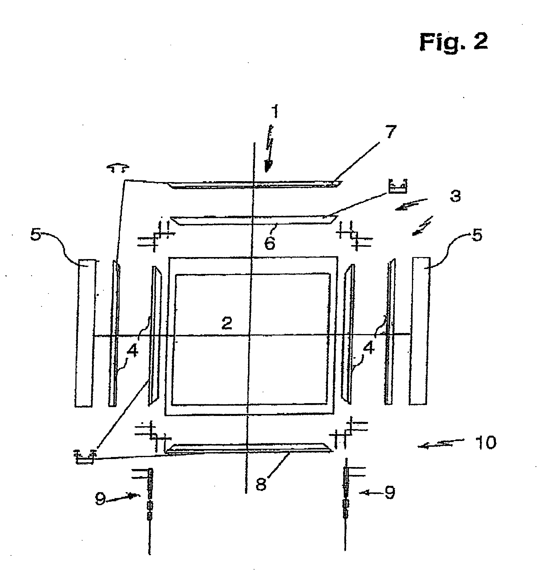
[0031]FIG. 2 shows the wall element 1 in an exploded representation, namely along with the wall panel 2 the respective frame parts and covers, i. e. the lateral frame parts 4 together with the lateral covers 5, the upper frame part 6 with the upper cover 7, and the lower frame part 8 which with the supporting feet 9 forms the base 10. The frame parts 4, 6, and 8 are made in the form of aluminum profiles. The covers 5 and 7 are also aluminum parts, where any materials can be used here.

[0032]FIG. 3 shows in two s...


PUM


Abstract

A partition wall comprising at least one wall element 1 which comprises front and rear wall panels 2 joined in a rectangular frame composed of lateral frame parts 4 and upper and lower frame parts 6 and 8. The lateral frame parts include two sets of opposing guide grooves 14 which permit the wall panels to be inserted into the frame by sliding the wall panels along the respective set of guide grooves.

Description

CROSS REFERENCE TO RELATED APPLICATION [0001] The present application is a continuation of international application PCT / DE2004 / 002088, filed 17 Sep. 2004, and which designates the U.S. The disclosure of the referenced application is incorporated herein by reference.BACKGROUND OF THE INVENTION [0002] The present invention relates to a partition wall composed of at least one wall element, where the wall element comprises at least one wall panel and frame parts at least partially enclosing the wall panel to form a frame. The wall panel can be a flat member covered with cloth, thus, for example, a textile-covered flat member which is disposed as a fixed panel in the frame. Finally, the wall panel can be any flat member, with or without applications. [0003] Partition walls of the generic type have long been known in practice. Only by way of example is reference made here to the German Utility Model DE 202 07 741 U1. [0004] The generic partition wall is, however, problematic in practice ...

Claims


Application Information

Patent Timeline
Patent Type & Authority Applications(United States)
IPC IPC(8): E04H1/00E04B2/74
CPCE04B2/7427E04B2002/742E04B2002/7461E04B2002/7479
Inventor KRAFT, PETER
Owner KRAFT PETER
Why Eureka
Try Eureka