

Accumulator with full-flow filtering
a filtering and accumulator technology, applied in refrigeration machines, lighting and heating apparatus, refrigeration components, etc., can solve the problems of system efficiency loss, compressor damage, and inability to evaporate all liquid, and achieve the effect of reducing the effect of accumulator function, size, installation, cost or complexity, and being easy to manufactur
- Summary
- Abstract
- Description
- Claims
- Application Information
AI Technical Summary
Benefits of technology
Problems solved by technology
Method used
Image

Examples
Embodiment Construction
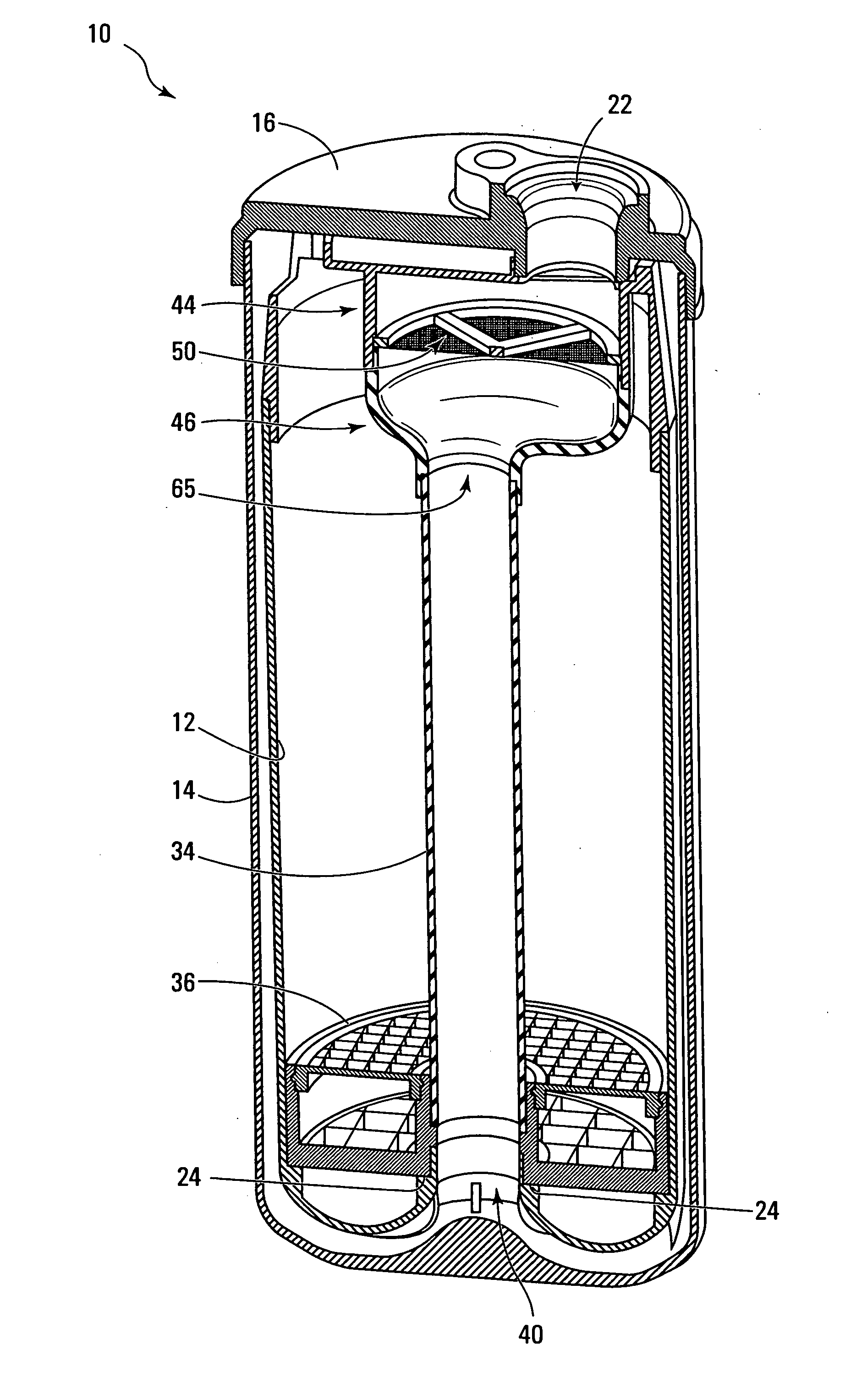
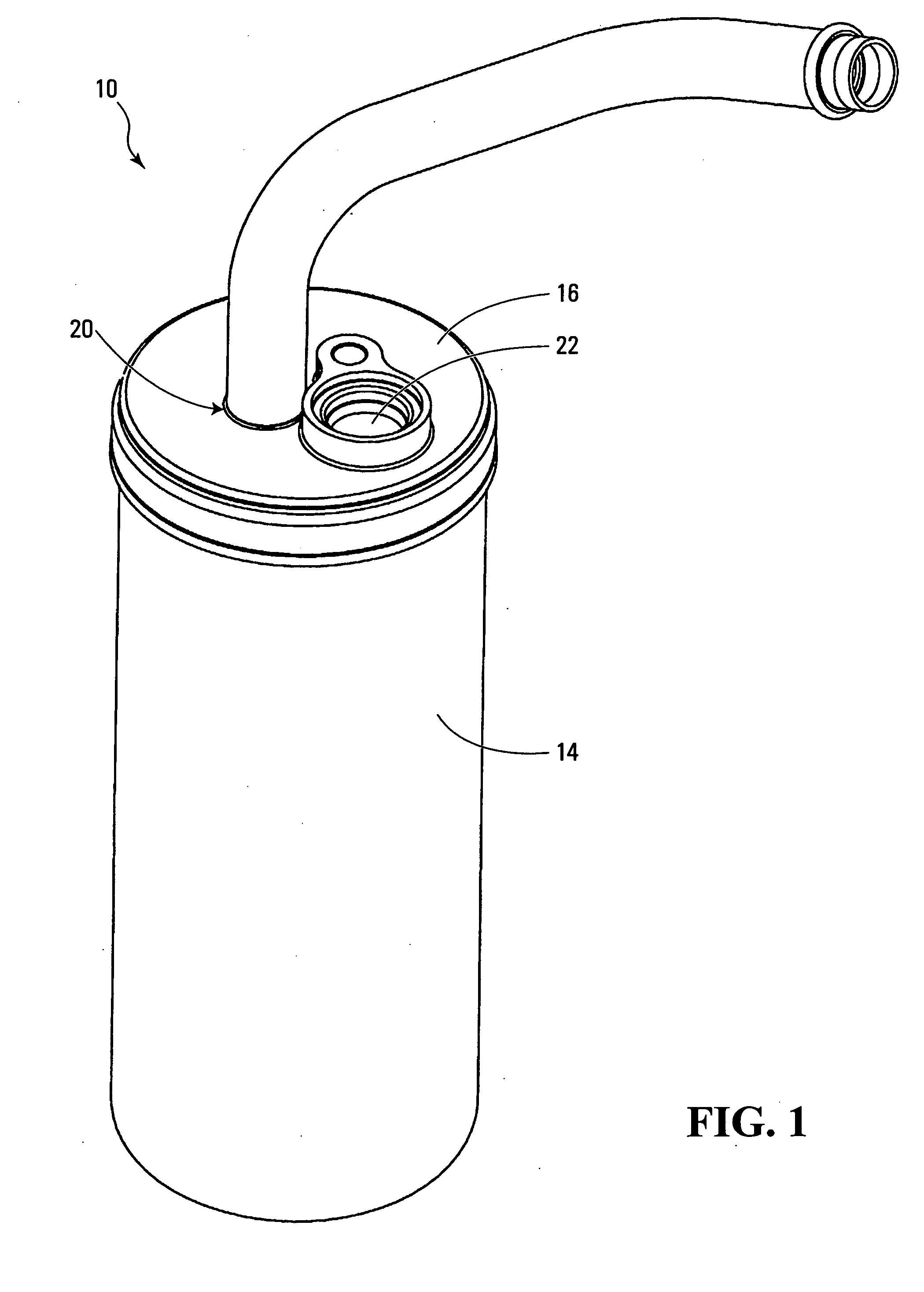
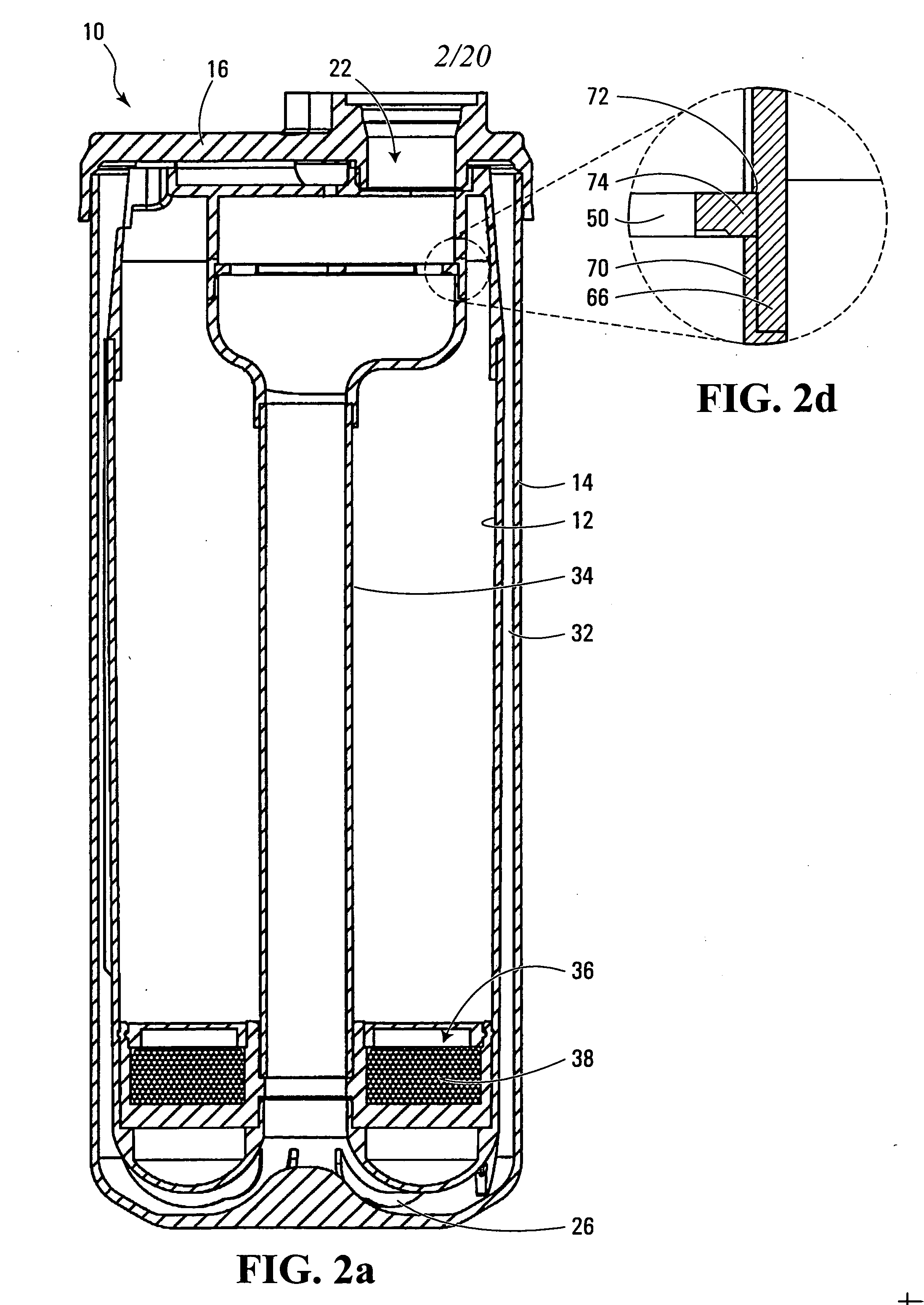
[0058] A representative accumulator 10 is shown in FIG. 1. A vertical sectional view of FIG. 1 is shown in FIG. 2a. The accumulator 10 of FIG. 2a is representative of a type having a liner 12. Different views of the accumulator of FIG. 2a are shown in FIGS. 2b-2e.
[0059] An outer container 14 of the accumulator 10 may be referred to as a can 14. The can 14 has a generally cylindrical shape, closed on its bottom end. A top portion 16 of the accumulator 10 is hermetically sealed to the can 14. The top portion 16 as shown in FIG. 1 has an inlet opening 20 (as perhaps best seen in FIG. 2e) and an outlet opening 22.
[0060] The liner 12 sits within the can 14. The liner 12 is generally cylindrical. The circumference of the liner 12 is generally concentric with the circumference of the can 14. A bottom portion of the liner 12 curves inward and upward, to form a generally circular stop 24 (see FIG. 2b). The liner 12 is spaced from the can 14 by feet 26 (as shown in FIG. 2a) and vertical spa...
PUM
 Abstract
Description
Claims
Application Information