Multi-purpose sleeve for tieback connector

a tieback connector and multi-purpose technology, applied in the direction of drilling machines and methods, drilling/well accessories, borehole/well accessories, etc., can solve the problems of wasting valuable rig time and affecting the sealing of components, and achieve the effect of facilitating the entry of the tieback connector and preventing damag

Inactive Publication Date: 2006-09-07
VETCO GRAY
View PDF9 Cites 37 Cited by
  • Summary
  • Abstract
  • Description
  • Claims
  • Application Information

AI Technical Summary

Benefits of technology

[0004] In this invention, a sleeve is installed on the tubular body of a component to be lowered from a surface vessel into a wellhead member. In the preferred embodiment, the component comprises a tieback connector. The sleeve has a lower position with a lower end adjacent to the seal to prevent damage. The exterior of the sleeve is configured to serve as a stab guide to facilitate entry of the tieback connector into the wellhead housing. The sleeve lands on an upward facing shoulder in the wellhead housing, which is typically the upper end of a casing hanger. Continued downward movement of the connector body causes the connector body to move downward relative to the sleeve. This downward movement results in the seal sliding into engagement with the sealing surface in the casing hanger.
[0005] The tieback connector has a latch member that moves into engagement with a locking profile in the bore of the wellhead housing. The upper end of the sleeve contacts the lower end of the latch member as the latch member engages the locking profile. As a result, any upward force exerted on the sleeve due to the casing hanger tending to move upward transmits through the sleeve, latch member and into the wellhead housing. This load path prevents upward movement of the casing hanger, which could otherwise cause damage to the seal.

Problems solved by technology

Often, the components will have seals that are subject to being damaged while lowering through openings in the floating platform and also while being stabbed into the wellhead assembly.
Normally, installing the lockdown member requires an extra trip to be made with a running tool, costing valuable rig time.

Method used


Image

  • Multi-purpose sleeve for tieback connector
  • Multi-purpose sleeve for tieback connector
  • Multi-purpose sleeve for tieback connector

Examples


Embodiment Construction

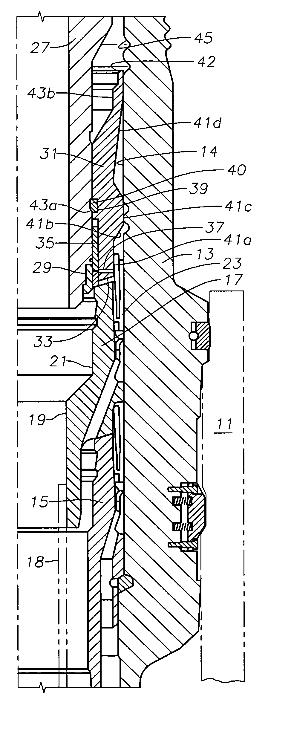
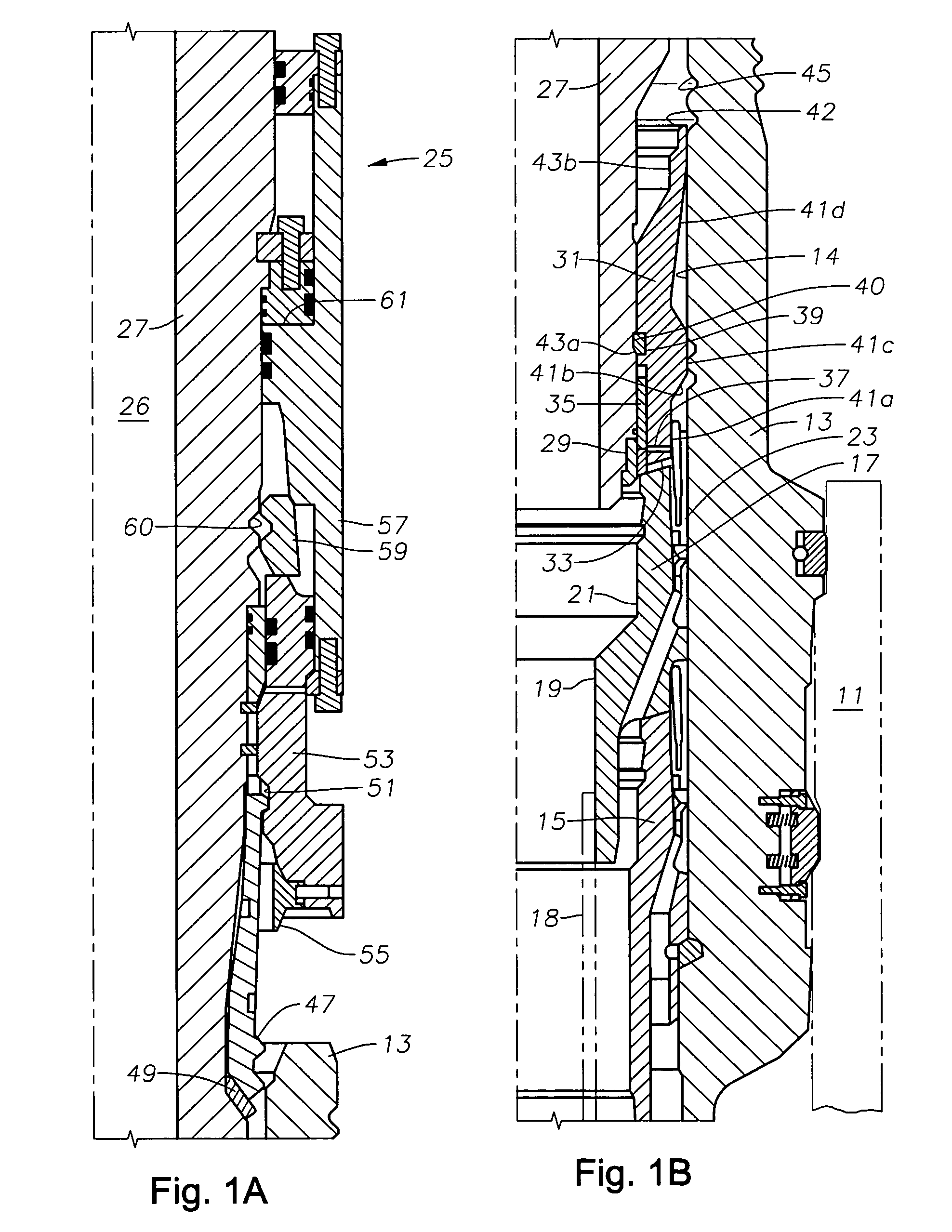
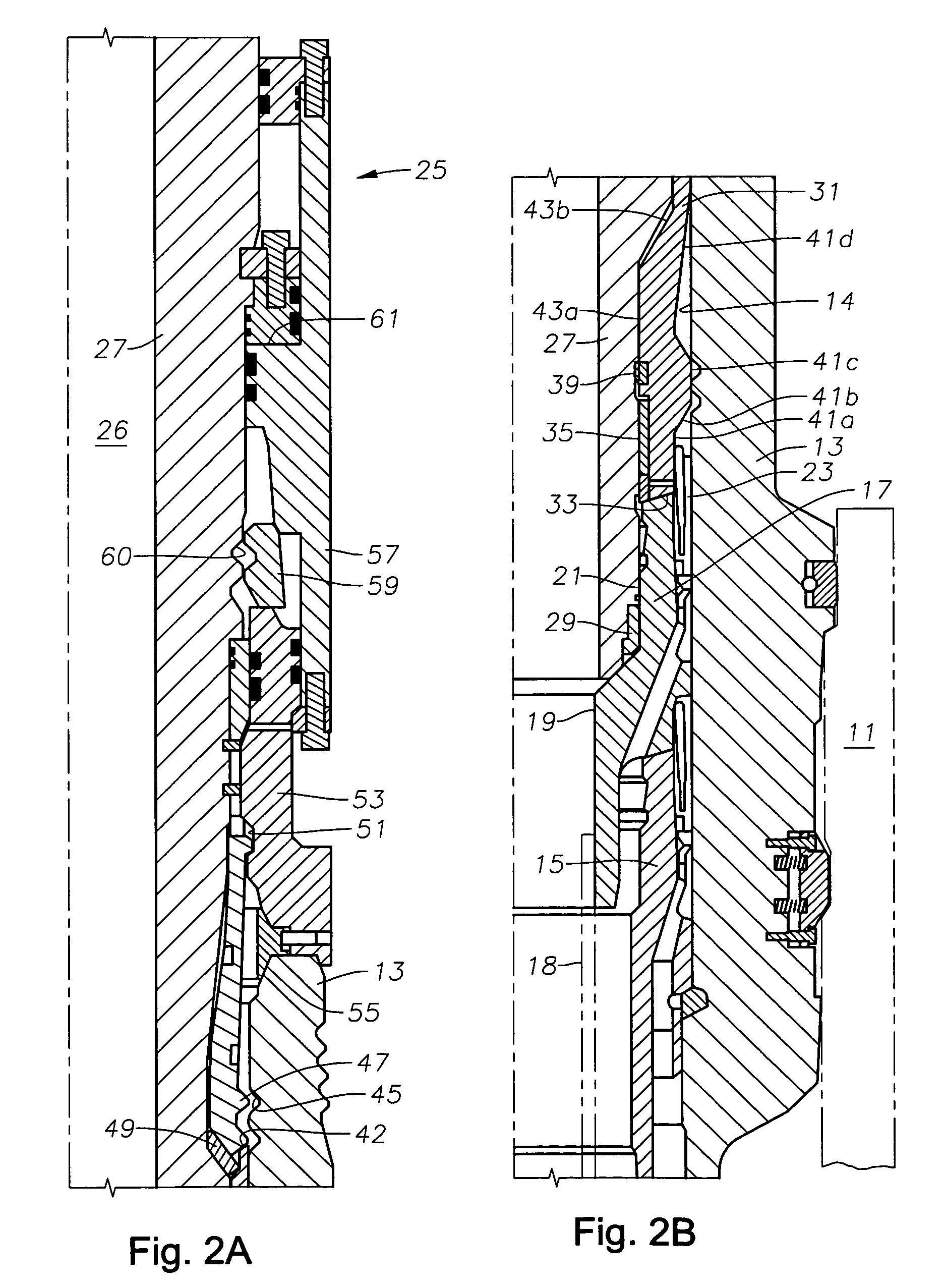
[0009] Referring to FIGS. 1A and 1B, a typical subsea wellhead assembly includes a low pressure or outer wellhead 11. Outer wellhead housing 11 is connected to a string of conductor pipe (not shown) that extends to a first depth in the well. An inner or high pressure wellhead housing 13 lands in low pressure wellhead 11. High pressure wellhead housing 13 is connected to casing (not shown) that extends into the well to a second depth. Wellhead housing 13 has a bore 14 into which at least one casing hanger 15 lands. In this embodiment, there are two casing hangers 15, 17, each of which is connected to a separate string of casing 18 extending into the well.

[0010] Casing hanger 17 has a bore 19 with an enlarged inner diameter in the upper portion containing a cylindrical seal surface 21. A packoff 23 seals between an exterior wall surface of casing hanger 17 and wellhead housing bore 14. It is not uncommon for a number of closely spaced wells to be drilled and installed with casing han...


PUM


Abstract

A tieback connector connects a riser between a subsea wellhead housing and a floating platform. The tieback connector has a tubular body that stabs into and seals with a casing hanger. A latch member on the tieback connector engages a locking profile to secure the tieback connector to the wellhead housing. A sleeve is slidably carried on the tubular body between a running-in position and a set position. The lower end of the sleeve lands on an upper rim of the casing hanger prior to the seal engaging the seal surface. Continued downward movement of the tubular body relative to the sleeve causes the seal to engage the seal surface and the sleeve to move to the set position. The sleeve has upper end that engages a lower end of the latch member to limit any upward movement of the casing hanger in the wellhead housing.

Description

BACKGROUND OF THE INVENTION [0001] A subsea wellhead assembly installed at the sea floor may be in water thousands of feet deep. During completion and certain production operations, components from a floating platform are lowered from the platform to engage the subsea wellhead assembly. Often, the components will have seals that are subject to being damaged while lowering through openings in the floating platform and also while being stabbed into the wellhead assembly. A remote operated vehicle (“ROV”) may be used to help stab and guide the component being lowered from the surface vessel. [0002] For example, one component comprises a tieback connector. A tieback connector connects a production riser between a subsea wellhead housing and the surface production platform. Typically a surface production tree locates at the upper end of the production riser on the production platform. A tieback connector normally has an tubular body with a lower end that stabs into the bore of a casing h...

Claims


Application Information

Patent Timeline
Patent Type & Authority Applications(United States)
IPC IPC(8): E21B33/076
CPCE21B33/038E21B33/03E21B33/035
Inventor PALLINI, JOSEPH W. JR.MCCARTY, JEFFERY K.
Owner VETCO GRAY
Why Eureka
Try Eureka