Integrated resolver for high pole count motors

a resolution device and high-poly count technology, applied in the field of motors, can solve the problems of limiting the use of the motor to the smaller temperature range of the attached encoder, and affecting the quality of the encoder

Inactive Publication Date: 2006-09-07
QUICKSILVER CONTROLS
View PDF40 Cites 21 Cited by
  • Summary
  • Abstract
  • Description
  • Claims
  • Application Information

AI Technical Summary

Problems solved by technology

On the other hand, encoders can be an expensive component in that an encoder can be a major portion of the costs of a motor.
Encoders require alignment and additional wiring and can add significantly to the assembly costs of a motor.
Encoders also typically have a temperature range that is smaller than the temperature range of the motor to which they are attached, limiting the use of the motor to the smaller temperature range of the attached encoder.
This can limit the power that can be practically achieved with the system due to the reduced temperature range.
When a resolver is implemented as an add on to an existing motor structure, it increases the cost of the components of the motor and also increases the assembly costs for the motor.
The design described in this patent is a complicated one that can be difficult to assemble.
Generally such contacts are difficult to make and can be unreliable.

Method used


Image

  • Integrated resolver for high pole count motors
  • Integrated resolver for high pole count motors
  • Integrated resolver for high pole count motors

Examples


Embodiment Construction

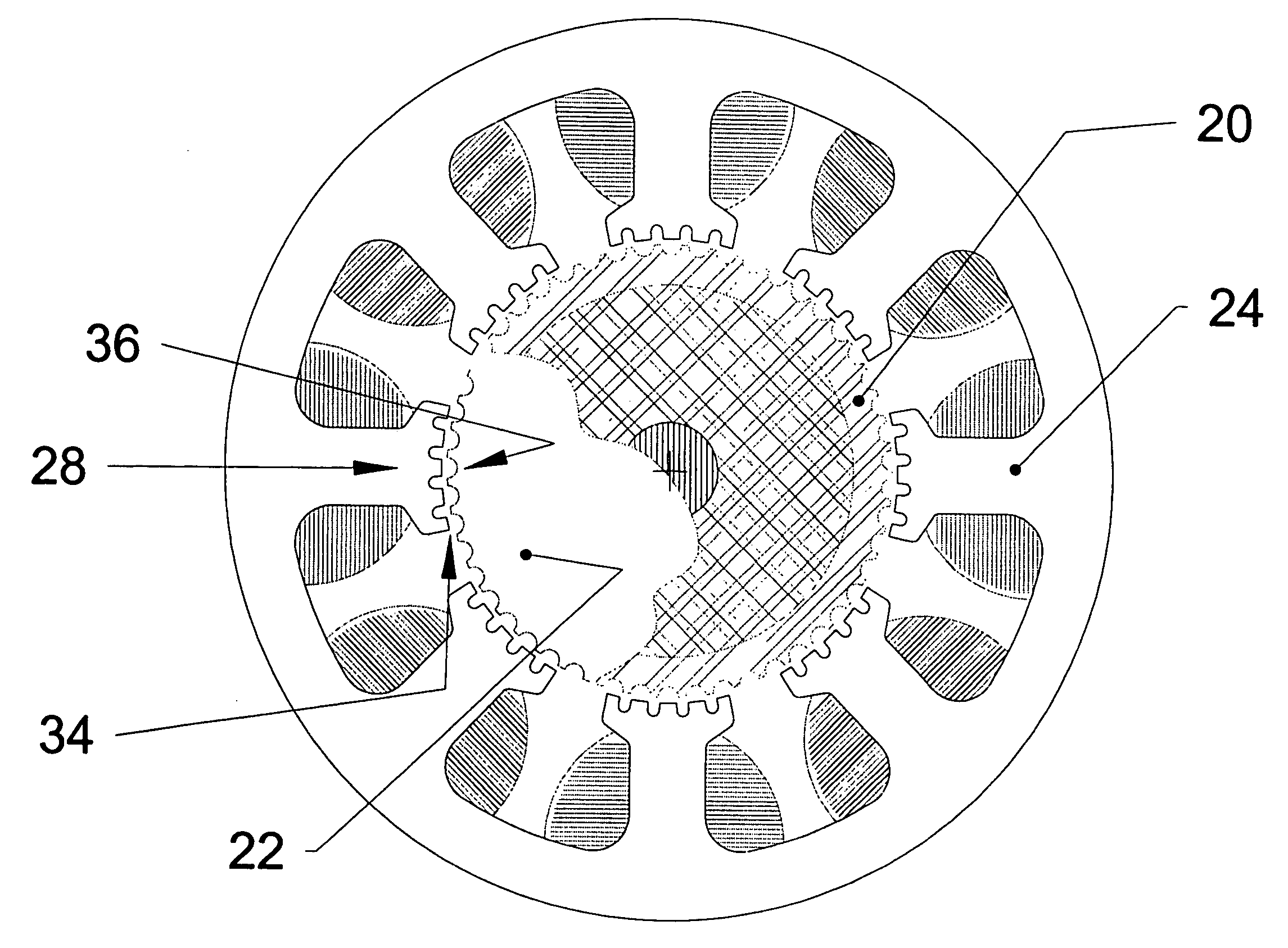
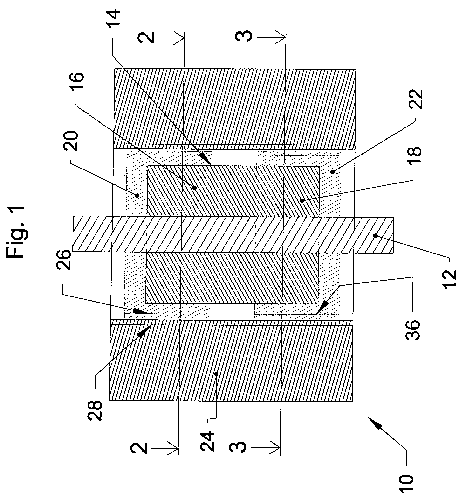
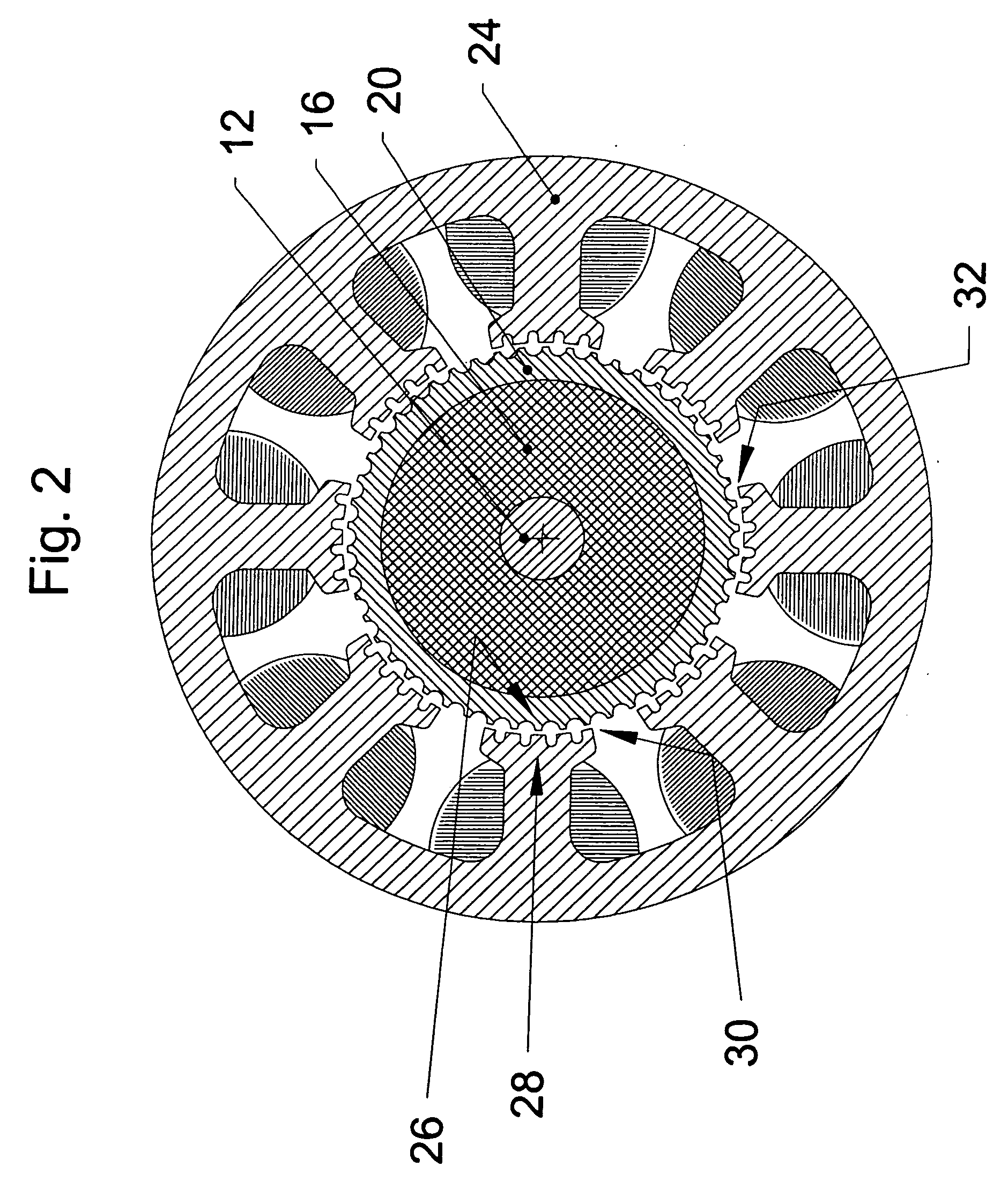
[0016] An aspect of the present invention provides an integrated motor-position sensor. The motor has a rotor assembly including a cylindrical portion having an axis, the cylindrical portion has a plurality of peripherally-spaced radially-projecting rotor teeth. The motor also has a stator assembly coaxial with the rotor assembly and having a plurality of radially projecting stator poles, the stator poles each have a plurality of stator teeth projecting radially to a circle coaxial with the rotor assembly, and coils for electrically energizing the stator poles. A plurality of sensing coils are positioned to intercept the magnetic flux between a plurality of the stator poles and a plurality of rotor teeth.

[0017] Another aspect of the invention provides an integrated motor-position sensor including a motor comprising a rotor assembly including a cylindrical portion having an axis, the cylindrical portion having a plurality of peripherally-spaced radially-projecting rotor teeth. The m...


PUM


Abstract

An AC synchronous motor, also known as a stepper motor, uses its magnetics and drive coils to produce both motion and excitation for sets of position sensing coils. Each drive phase is equipped with one or more sensing coils, which may be differentially wound, with the coils configured to act as secondaries of a linear variable differential transformer (LVDT). The primary of the so-formed LVDT is the motor drive winding. The outputs from these coils are fed to a microprocessor or DSP through an internal or external A / D converter. The microprocessor or DSP decodes the measured voltages using resolver strategies to produce a position measurement. An alternate mode of operation uses these same coils to form a variable reluctance resolver. This alternative mode of operation could be used for sensing coarse position while the motor drive is not energized.

Description

RELATED APPLICATIONS [0001] This application claims priority under 35 U.S.C. §§ 120 & 121 from U.S. patent application Ser. No. 10 / 217,744 filed Aug. 13, 2002, which application is hereby incorporated by reference in its entirety.BACKGROUND [0002] 1. Field of the Invention [0003] This invention relates to a motor having a resolver for detecting a position, velocity or acceleration that is determined by the motor and in a specific application, to such a motor associated with a control system that uses the position, velocity or acceleration in controlling the motor. [0004] 2. Description of the Related Art [0005] Motors are used in a variety of applications for effecting the controlled motion of objects. For example, motors are used in a variety of industrial automation and other automation applications. In many applications, it is useful to provide the motor or the motor's controller with an accurate measure of the motor position to allow for greater precision in positioning objects ...

Claims


Application Information

Patent Timeline
Patent Type & Authority Applications(United States)
IPC IPC(8): H02K11/00H02K19/00H02K41/00H02K23/66H02K21/00
CPCH02K11/0031H02K29/12H02K41/03H02K2201/18H02K11/225
Inventor LABRIOLA, DONALD P. II
Owner QUICKSILVER CONTROLS
Why Eureka
Try Eureka