Digital camera for correcting tilted image

a digital camera and image correction technology, applied in the field of digital cameras, can solve the problems of awkward use of holding devices by the operator of the camera,

Inactive Publication Date: 2006-09-07
FUJIFILM CORP +1
View PDF9 Cites 101 Cited by
  • Summary
  • Abstract
  • Description
  • Claims
  • Application Information

AI Technical Summary

Problems solved by technology

However, the problem with the holding device stated above is that the operator of the camera has to insert the hook portions formed at the lower end of the holding portion into the s

Method used


Image

  • Digital camera for correcting tilted image
  • Digital camera for correcting tilted image
  • Digital camera for correcting tilted image

Examples


Embodiment Construction

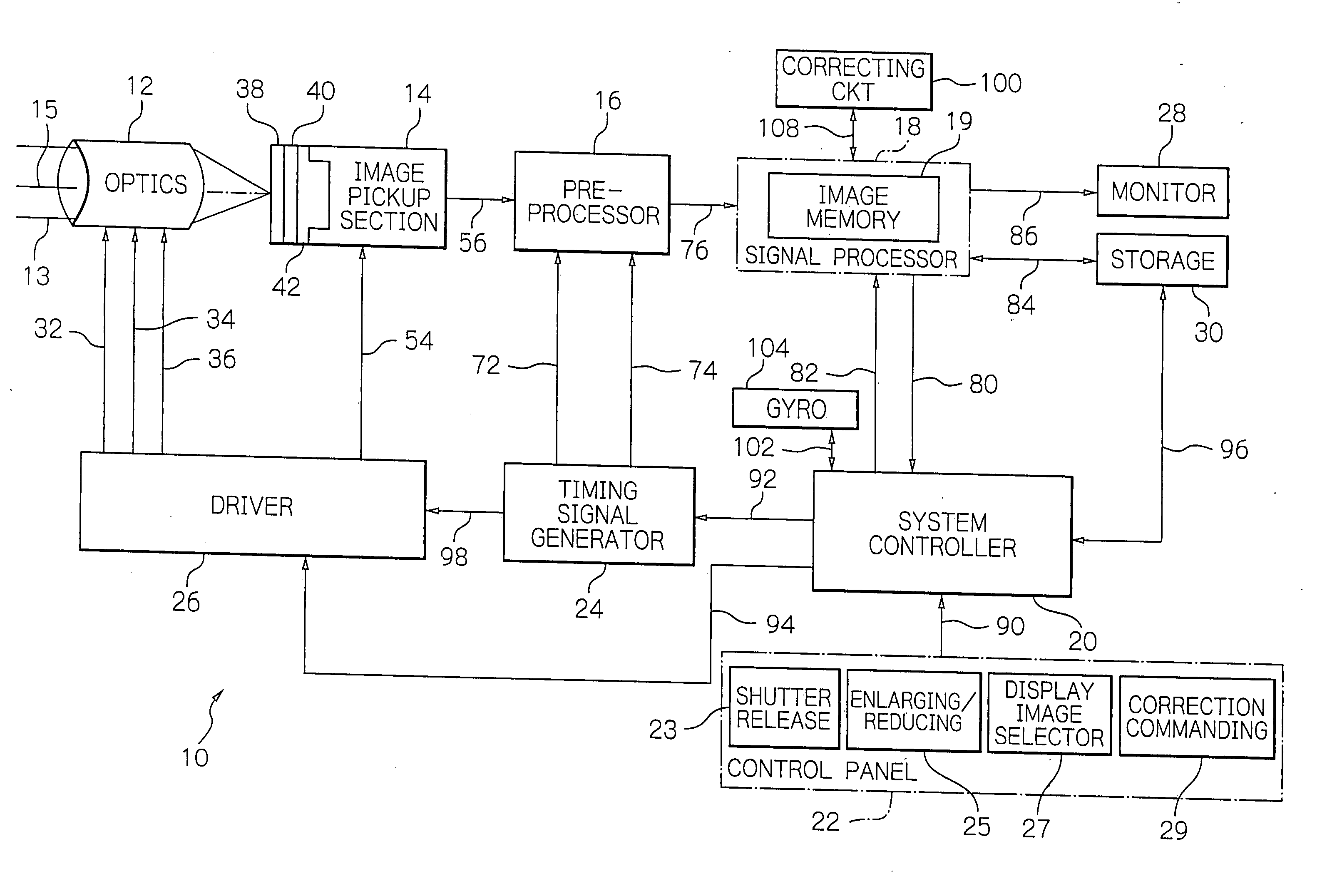
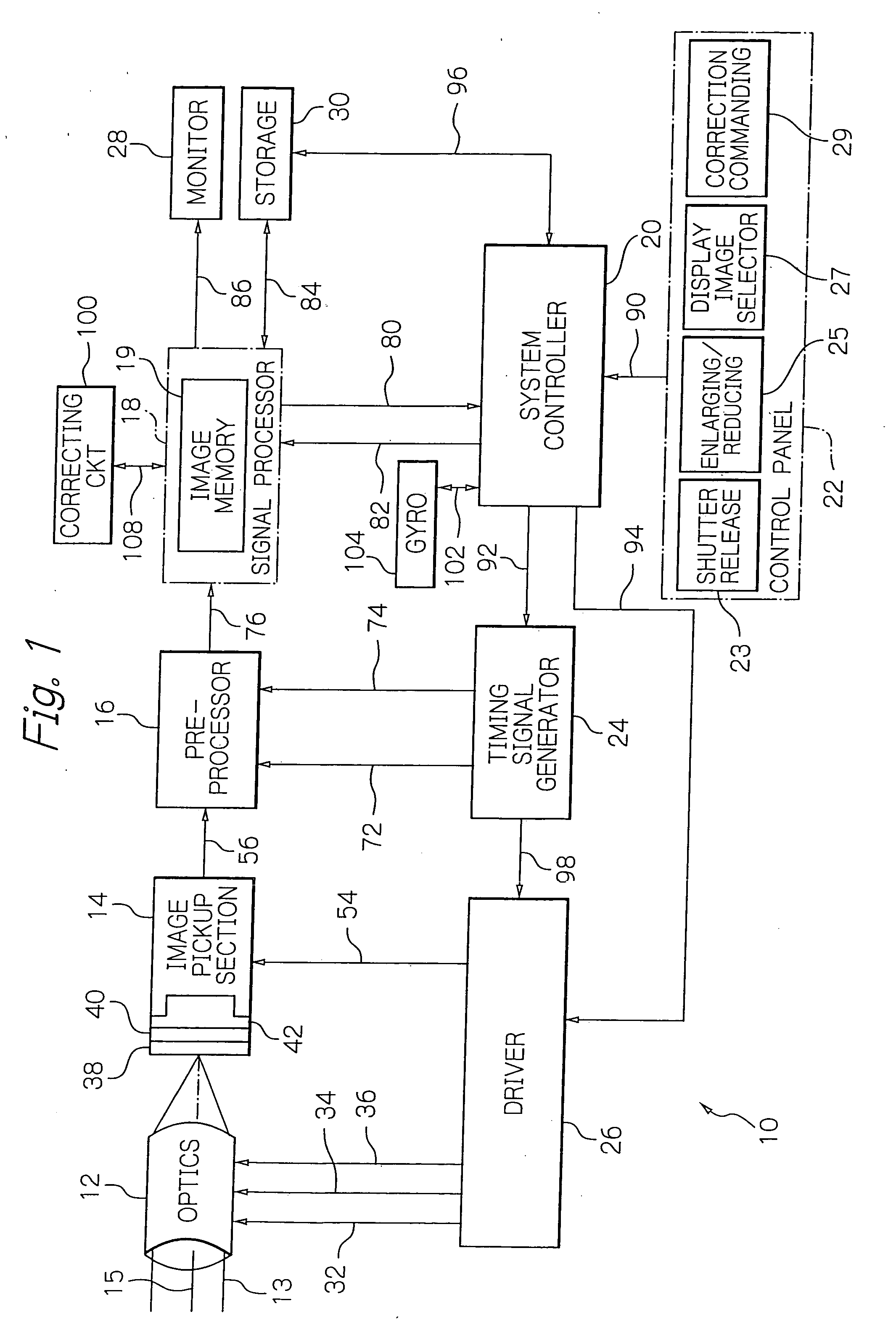
[0020] Referring to FIG. 1 of the accompanying drawings, a digital camera embodying the present invention, generally 10, includes an optics 12, an image pickup section 14, a preprocessor 16, a signal processor 18, a system controller 20, a control panel 22, a timing signal generator 24, a driver 26, a video monitor or display 28, a storage 30, an image correcting circuit 100 and a gyroscope or angle sensor 104, which are interconnected as illustrated. It is to be noted that part of the illustrative embodiment not directly relevant to the understanding of the present invention is not shown, and detailed description thereof will not be made in order to avoid redundancy. The optics 12 includes a mechanical shutter, a lens system, a zoom mechanism, an iris control mechanism and an automatic focus (AF) control mechanism, although not shown specifically. The optics 12 is configured to conduct light 13 incident from an imaging field through the lens system to the image pickup section 14 wi...


PUM


Abstract

A digital camera includes a gyroscope for sensing an angle by which the image sensing surface of the camera is tilted relative to the horizontal direction. A system controller, when receiving the tilt angle from the gyroscope, adds the tilt angle to image data temporarily stored in an image memory, which is included in a signal processor, in the form of tag information. A correcting circuit rotates the image in the opposite direction by the tilt angle in accordance with the tag information added to image data and causes a monitor to display the resulting image. The digital camera thus produces the image to be displayed in its adequate position without resorting to any device for holding the camera in its adequate position.

Description

BACKGROUND OF THE INVENTION [0001] 1. Field of the Invention [0002] The present invention relates to a digital camera for picking up an image of a subject field to reproduce or display the image picked up. [0003] 2. Description of the Background Art [0004] A digital camera is sometimes required to be held in an adequate position when shooting a desired subject because, if the position of the camera is not adequate, the subject is displayed on its display monitor screen, which is usually rectangular, in a tilted position with respect to the frame of the screen. The tilt of a captured subject image displayed on the monitor screen is caused when the camera is positioned with its reference direction, such as either one of the edges of the imaging frame formed by its photosensitive array, or image sensing surface, is not coincident with the actual horizontal direction in the field including the intended subject. In light of this, it has been customary to provide a digital camera with a l...

Claims


Application Information

Patent Timeline
IPC IPC(8): H04N5/225
CPCH04N5/23293H04N5/2628H04N5/272H04N23/651H04N23/63H04N23/843
Inventor YOSHIMATSU, EIJI
Owner FUJIFILM CORP
Why Eureka
Try Eureka