Illuminating device utilizing light-emitting diode array
- Summary
- Abstract
- Description
- Claims
- Application Information
AI Technical Summary
Benefits of technology
Problems solved by technology
Method used
Image
Examples
first embodiment
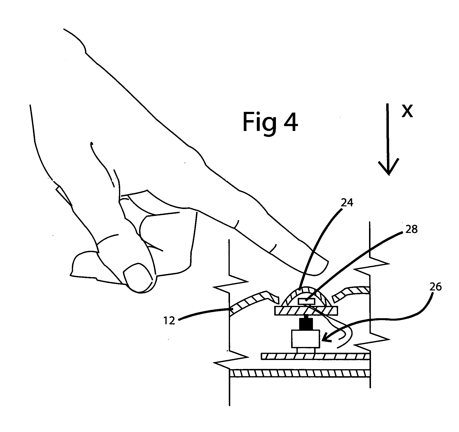
[0026] Referring to FIGS. 5-7, there is shown an electrical circuit 30 for nightlight 10 in accordance with the present invention. Circuit 30 includes three LEDs 16, 18, 20 connected in series with an AC source (not shown) via prongs 22. It will be understood that circuit 30 could, however, include only one LED or could include more than three LEDs without departing from the spirit of the present invention. Circuit 30 includes a photo-diode circuit, well known in the art and identified by box 32. Circuit 30 further includes capacitors 34, 36, a rectifier 38 to change alternating current from the power source to direct current, and resistors 40 and 42. Switch 26 is provided to selectively route current through a resistor 44. When switch 26 is open, current does not flow through resistor 44 and consequently the maximum amount of current flows through LEDs 16, 18, 20 and the maximum possible amount of light is emitted by LEDs 16, 18 and 20. This situation is illustrated in FIG. 6, wher...
second embodiment
[0027] Referring to FIGS. 8-9 there is shown an electrical circuit for nightlight in accordance with the present invention and referenced by the number 130. In circuit 130, LEDs 116, 118 and 120 are connected in series with an AC power source (not shown) via prongs 122; and to a well-known photo-diode circuit represented by box 132. Circuit 130 includes two capacitors 134 and 136; a rectifier 138 and biasing resistors 140, 142 and 144. Switch 126 is connected into circuit 130 so that when switch 126 is activated, current can be routed through either all three LEDs 116, 118 and 120 or one of the LEDs, namely 120, can be cut out of circuit 130. When switch 126 is in a first position, current flows through the pathway represented by “A”(FIG. 8) and all three LEDs 116, 118 and 120 are on. When switch 126 is in a second position, current flows through the pathway represented by “B” and through resistor 144. In this second instance, only LEDs 116 and 118 are illuminated. As a consequence,...
third embodiment
[0028] Referring to FIGS. 10-11 there is shown an electrical circuit for nightlight in accordance with the present invention and referenced by the number 230. In circuit 230, LEDs 216, 218 and 220 are connected in series with an AC power source (not shown) via prongs 222; and to a well-known photo-diode circuit represented by box 232. Circuit 230 includes two capacitors 234 and 236; a rectifier 238 and biasing resistors 240, 242 and 244. A two-way switch 226 is provided to selectively route current through all three LEDs 216, 218 and 220; or through only one of the LEDs, namely bulb 216. When switch 226 is in a first position, current flows through the pathway represented by “C” (FIG. 10) and all three LEDs 216, 218 and 220 are illuminated. When switch 226 is in a second position, current flows through the pathway represented by “D” and through resistor 244. In this second instance, only LED 216 is illuminated. As a consequence, the light emitted by nightlight is substantially dimme...
PUM
 Abstract
Description
Claims
Application Information
 - R&D
- Intellectual Property
- Life Sciences
- Materials
- Tech Scout
- Unparalleled Data Quality
- Higher Quality Content
- 60% Fewer Hallucinations
Browse by: Latest US Patents, China's latest patents, Technical Efficacy Thesaurus, Application Domain, Technology Topic, Popular Technical Reports.
© 2025 PatSnap. All rights reserved.Legal|Privacy policy|Modern Slavery Act Transparency Statement|Sitemap|About US| Contact US: help@patsnap.com


