Method of and Apparatus for Image Enhancement

a technology of image enhancement and apparatus, applied in the field of image processing, can solve the problems of deteriorating signal to noise ratio, low electron well capacity, and a noise reduction algorithm that is typically a few generations old, and achieves noise reduction, noise reduction, and improved sharpness and masking of image processing pipeline artifacts.

Inactive Publication Date: 2013-12-12
APPLE INC
View PDF16 Cites 24 Cited by
  • Summary
  • Abstract
  • Description
  • Claims
  • Application Information

AI Technical Summary

Benefits of technology

[0012]Embodiments according to the present invention provide image enhancement by separating the image signals, either Y or RGB, into a series of bands and performing noise reduction on bands below a given frequency but not on bands above that frequency. The bands are summed to develop the image enhanced signals. This results in improved sharpness and masking of image processing pipeline artifacts. Chroma signals are not separated into bands and noise reduction is applied. The higher frequency band is attenuated or amplified based on light level. The noise reduction has thresholds based on measured parameters, such as signal frequency, gain and light level, provided in a lookup table. The window size used for the noise reduction varies with the light level as well, smaller windows sizes being used in bright light and increasing window sizes as light levels decrease. Panoramic images are handled in a similar fashion.

Problems solved by technology

This problem is very significant in mobile phone or point-and-shoot camera where pixels are much smaller than DSLR sensors, hence they have lower electron well capacity, further deteriorating the signal to noise ratio, especially in low-light situations.
It is constrained by the number of delay lines available for the image signal processor as well as computational limitations.
Second, since it takes a few years to design, test, and produce an image signal processor, so the noise reduction algorithm is typically a few generations old.
These artifacts severely degrade image quality in bright light, especially in the sky regions (aka blue-sky noise), but they are especially severe in low-light.
This averaging alters the noise characteristics of the overlapped regions, giving the panorama a non-uniform look.
A second issue with panorama is that to minimize motion blur, the exposure time is decreased.
This mitigates motion blur, but results in severe noise in low-light, in both the luminance and chrominance channels.
This operation is highly non-linear and content dependent, and therefore is not easily modeled in the frequency domain.
Owing to the complicated nature of image degradations in the processed domain, classical full-band, fixed threshold, schemes do not work very well, as described in U.S. Pat. No. 8,108,211.
For example, since the noise is frequency dependent, if noise reduction algorithm parameters are chosen to remove noise of a certain frequency, for other frequencies the denoising will be either too much or too little, since the noise power varies with frequency.
Second, they split the frequency band in multiples of two, which may not be desirable or needed.
There are several problems with this approach.
Since pipeline artifacts share the same frequency band as structure, they cannot be modeled as noise and therefore cannot be mitigated without affecting the underlying image.
However, it does not address noise reduction, both spatial as well as temporal, which are also a part of any camera pipeline.
So at best the noise prediction is sub-optimal, hence, the noise reduction will not work as well as advertised.
However, as camera pipelines evolve and new features are added, the frequency domain characteristics of some highly non-linear operations, such as temporal and spatial noise reduction earlier in the pipeline, high dynamic range image formation, panorama stitching artifacts, more complex demosaicking algorithms, etc., and pipeline artifacts are hard to model.

Method used


Image

  • Method of and Apparatus for Image Enhancement
  • Method of and Apparatus for Image Enhancement
  • Method of and Apparatus for Image Enhancement

Examples


Embodiment Construction

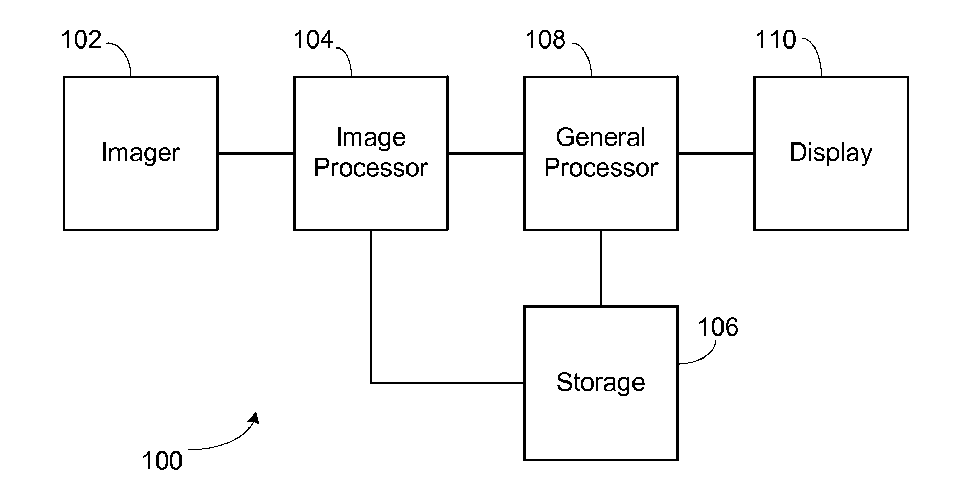
[0020]FIG. 1 is a block diagram of an exemplary device 100, such as a camera or phone. An imager 102, as typical in such devices, is connected to an image processor 104. The image processor 104 is connected to storage106 for both processing storage and longer term storage after completion of processing. The image processor 104 is also connected to a general processor 106 which performs more general duties. The general processor 108 is connected to a display no for providing a user the ability to view the current or previously stored images which the general processor 108 retrieves from storage 106. Storage 106 also stores the firmware and other software used by the image processor 104 and general processor 106 that perform the preferred embodiments. This is a very general overview and many variations can be developed, such as combining the image processor and general processor or forming the image processor using hardware, FPGAs, or programmed DSPs or some combination, as known to t...


PUM


Abstract

Image enhancement by separating the image signals, either Y or RGB, into a series of bands and performing noise reduction on bands below a given frequency but not on bands above that frequency. The bands are summed to develop the image enhanced signals. This results in improved sharpness and masking of image processing pipeline artifacts. Chroma signals are not separated into bands but have noise reduction applied to the full bandwidth signals. The higher frequency band is attenuated or amplified based on light level. The noise reduction has thresholds based on measured parameters, such as signal frequency, gain and light level, provided in a lookup table. The window size used for the noise reduction varies with the light level as well, smaller windows sizes being used in bright light and increasing window sizes as light levels decrease. Panoramic images are handled in a similar fashion.

Description

CROSS REFERENCE TO RELATED APPLICATIONS[0001]This application claims the benefit under 35 U.S.C. §119(e) of U.S. Provisional Patent Application Ser. No. 61 / 656,078 entitled “Method of and Apparatus for Image Enhancement,” filed Jun. 6, 2012, which is hereby incorporated by reference.BACKGROUND OF THE INVENTION[0002]1. Field of the Invention[0003]The invention is related to image processing of captured images[0004]2. Description of the Related Art[0005]At the image sensor, noise can be considered to be white (no frequency dependence) with a signal dependent variance due to shot noise. It is largely un-correlated between channels (R, G, B). At the end of the pipeline (after undergoing noise reduction, demosaicking, white balancing, filtering, color enhancement, and compression in the image signal processor), image noise is dependent on signal, frequency, illuminant, and light level, and is also correlated between channels as described in U.S. Pat. No. 8,108,211, hereby incorporated by...

Claims


Application Information

Patent Timeline
Patent Type & Authority Applications(United States)
IPC IPC(8): H04N5/217H04N7/00
CPCH04N9/77G06T5/002G06T2207/20016H04N23/81H04N23/60H04N23/698H04N23/10H04N23/843
Inventor BAQAI, FARHAN A.WONG, VINCENT Y.SACHS, TODD S.
Owner APPLE INC
Why Eureka
Try Eureka