Cervical intervertebral stabilizer

a cervical intervertebral stabilizer and stabilizer technology, applied in the field of cervical intervertebral stabilizer, can solve the problems of reducing the usefulness of the replacement option, affecting and affecting the ability of the patient to reproduce the natural stiffness of the intervertebral dis

Inactive Publication Date: 2006-09-07
CARDO MEDICAL
View PDF33 Cites 165 Cited by
  • Summary
  • Abstract
  • Description
  • Claims
  • Application Information

AI Technical Summary

Problems solved by technology

However, a disadvantage of this disc type is that the elastomer cushion experiences long term in-vivo problems stemming from microcracking, which detracts from its usefulness as a replacement option.
Furthermore, attachment of the flexible elastomer cushion to rigid endplates presents additional difficulties.
The ball and socket arrangement is adept in restoring “motion” of the spine, but, is poor in replicating the natural stiffness of the intervertebral disc.
This hybrid disc provides several advantages with respect to load carrying ability, but, is generally complex requiring a number of individual components.
Furthermore, long term in vivo difficulties with the elastomer cushion remain a concern as well as wear of the ball and socket arrangement.
The abrupt load paths can lead to high stress regions, which can detract from the appropriate biomechanical performance, i.e., strength, flexibility, and range-of-motion, of the prosthesis.
All of the above intervertebral devices suffer from common problems, for example, they are limited in the reaction forces that they produce in response to compressive forces.
This is undesirable in some applications.
Further, the above described devices are not suitable for posterior implantation.
Still further the above described devices are difficult to implant, reposition, or remove.

Method used


Image

  • Cervical intervertebral stabilizer
  • Cervical intervertebral stabilizer
  • Cervical intervertebral stabilizer

Examples


Embodiment Construction

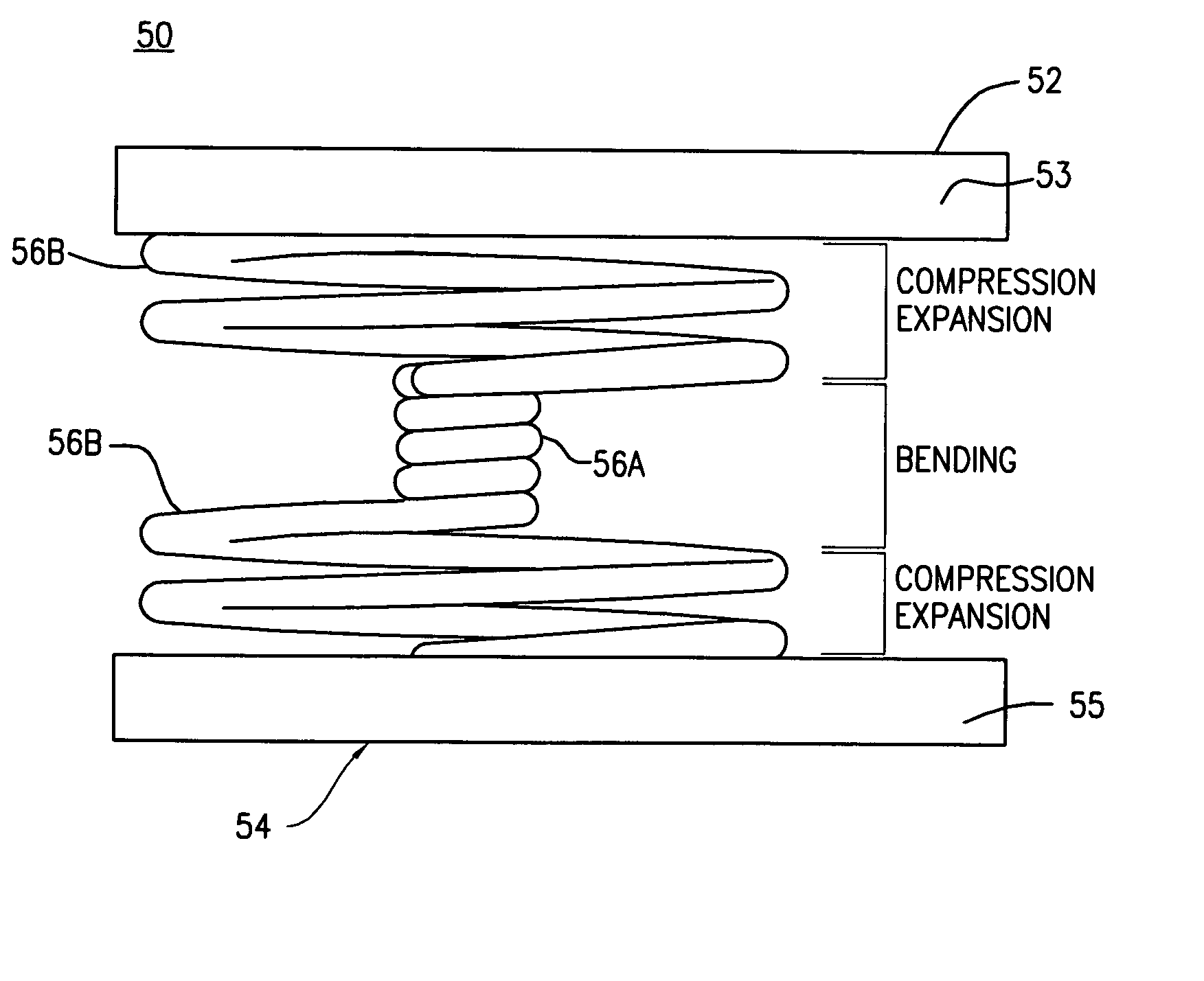
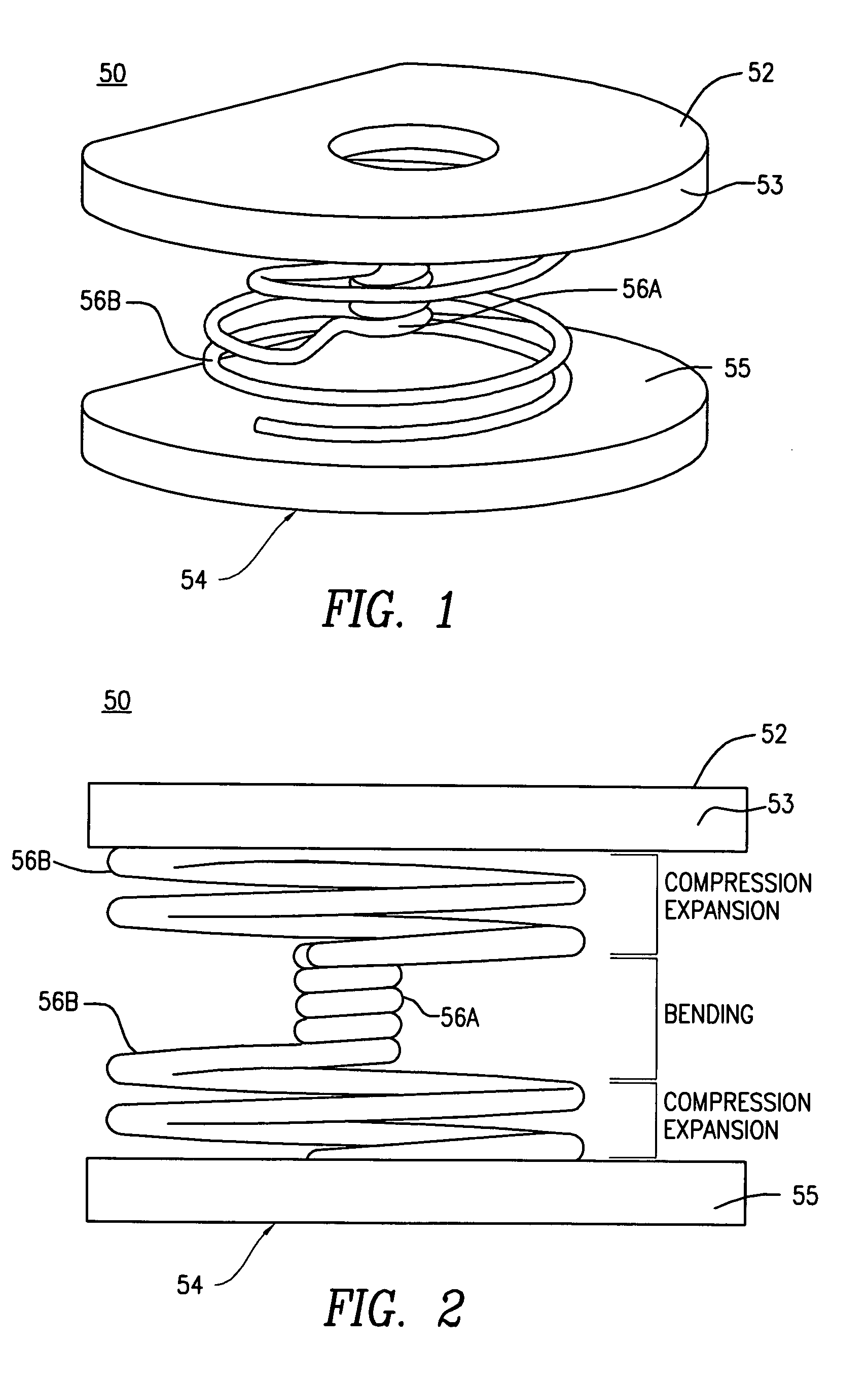
[0035]FIGS. 1-2 illustrate an embodiment of a spinal intervertebral stabilizer 50 in accordance with one or more aspects of the present invention. The stabilizer 50 is sized and shaped to fit in the intervertebral space between adjacent vertebral bones of the spine. It is understood that the size and shape of the stabilizer 50 may be adapted to fit in an intervertebral space at any level of the spine, such as the cervical spine, thoracic spine, or lumbar spine. The stabilizer 50 is sized and shaped to be inserted into the inter-vertebral space from an anterior direction. The stabilizer 50 includes an upper surface 52 of a first member 53 and a lower surface 54 of a second member 55 that are operable to engage end plates of the respective vertebral bones. A spring element in the form of a helical coil 56 is interposed between the upper and lower surfaces 52, 54 of the first and second members 53, 55.

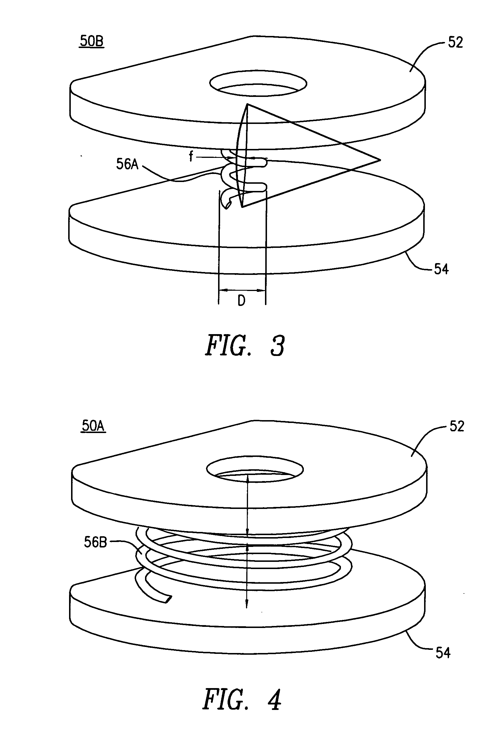
[0036] The helical coil 56 includes at least one first segment 56A having a first di...


PUM


Abstract

A cervical intervertebral stabilizer for a cervical region of a spine includes: a first surface operable to engage an endplate of a first vertebral bone of a spine; a second surface spaced apart from the first surface and operable to engage an endplate of an adjacent second vertebral bone of the spine; a spring element including at least one of: (i) a helical wound spring; and (ii) a hollow body having at least one slit forming a plurality of annular circumferential helical coils, the spring element being disposed between the first and second surfaces and being operable to provide reactive force in response to compression loads from the first and second vertebral bones, wherein at least some diameters of respective turns of the helical coils differ.

Description

CROSS REFERENCE TO RELATED APPLICATIONS [0001] This application claims the benefit of U.S. Provisional Patent Application No.: 60 / 658,345, filed Mar. 3, 2005, the entire disclosure of which is hereby incorporated by reference.BACKGROUND [0002] The present disclosure generally relates to apparatus and methods for treatment of spinal disorders using an intervertebral prosthesis which is disposed in an intervertebral disc space following removal of a damaged or diseased intervertebral disc. [0003] The objective in intervertebral disc replacement or intervertebral stabilization is to provide a prosthetic disc that combines both stability to support the high loads of the patient's vertebrae and flexibility to provide the patient with sufficient mobility and proper spinal column load distribution. [0004] Numerous artificial intervertebral discs for replacing a part or all of a removed disc have been developed, namely, elastomer discs, ball and socket discs, mechanical spring discs and hyb...

Claims


Application Information

Patent Timeline
Patent Type & Authority Applications(United States)
IPC IPC(8): A61F2/44
CPCA61B2017/0256A61F2/44A61F2/442A61F2/4611A61F2/4684A61F2002/30014A61F2002/3013A61F2002/30133A61F2002/30235A61F2002/30327A61F2002/30331A61F2002/3038A61F2002/30429A61F2002/30566A61F2002/30578A61F2002/30594A61F2002/30596A61F2002/30616A61F2002/30772A61F2002/30795A61F2002/30841A61F2002/30878A61F2002/448A61F2002/4619A61F2002/4627A61F2002/4628A61F2002/4629A61F2220/0025A61F2220/0033A61F2230/001A61F2230/0015A61F2230/0069A61F2250/0018A61F2250/0039
Inventor ROTHMAN, RICHARD H.ZUBOK, RAFAILKVITNITSKY, MIKHAIL
Owner CARDO MEDICAL
Why Eureka
Try Eureka