
Sharpness tester

a tester and sharpness technology, applied in the field of sharpness testers, can solve the problems of not being able to accurately locate the blunt/sharp parts of the blade, not having a known method of directly, accurately, reliably, repeatably and non-destructively measuring the cutting ability of the blade, etc., and achieves minimal damage to the edge

Active Publication Date: 2006-09-14
DOWD PETER CHRISTOPHER
View PDF3 Cites 28 Cited by
  • Summary
  • Abstract
  • Description
  • Claims
  • Application Information

AI Technical Summary

Benefits of technology

[0003] The object of the present invention is to provide a sharpness tester whereby an objective and quantifiable test of the sharpness of a blade along multiple parts of the blade can be achieved and in manner, which ensures damage to the edge, is minimal.

Problems solved by technology

Currently there is no known method of directly, accurately, reliably, repeatably and non-destructively measuring the cutting ability of a blade.
These methods do not provide the ability to accurately locate blunt / sharp portions of a blade.

Method used


Image

  • Sharpness tester
  • Sharpness tester
  • Sharpness tester

Examples


Embodiment Construction

according to one preferred embodiment reference will be made to the accompanying drawings in which:—

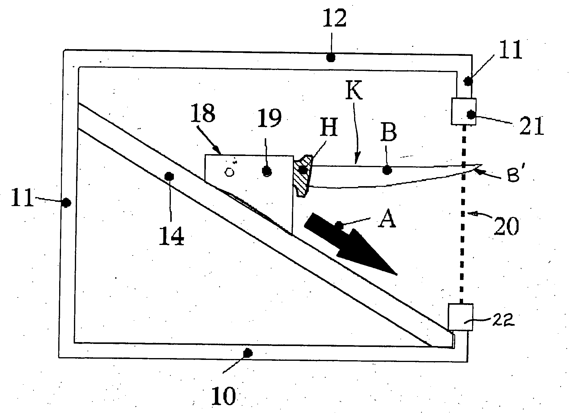
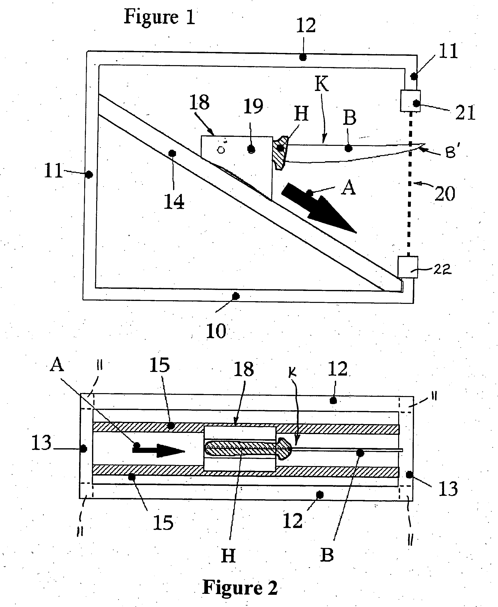
[0014]FIG. 1 is a side elevation view of the sharpness tester with a handled knife clamped in the blade holder and the blade performing a cutting action on the material,

[0015]FIG. 2 is an upper perspective view of the sharpness tester as shown in FIG. 1,

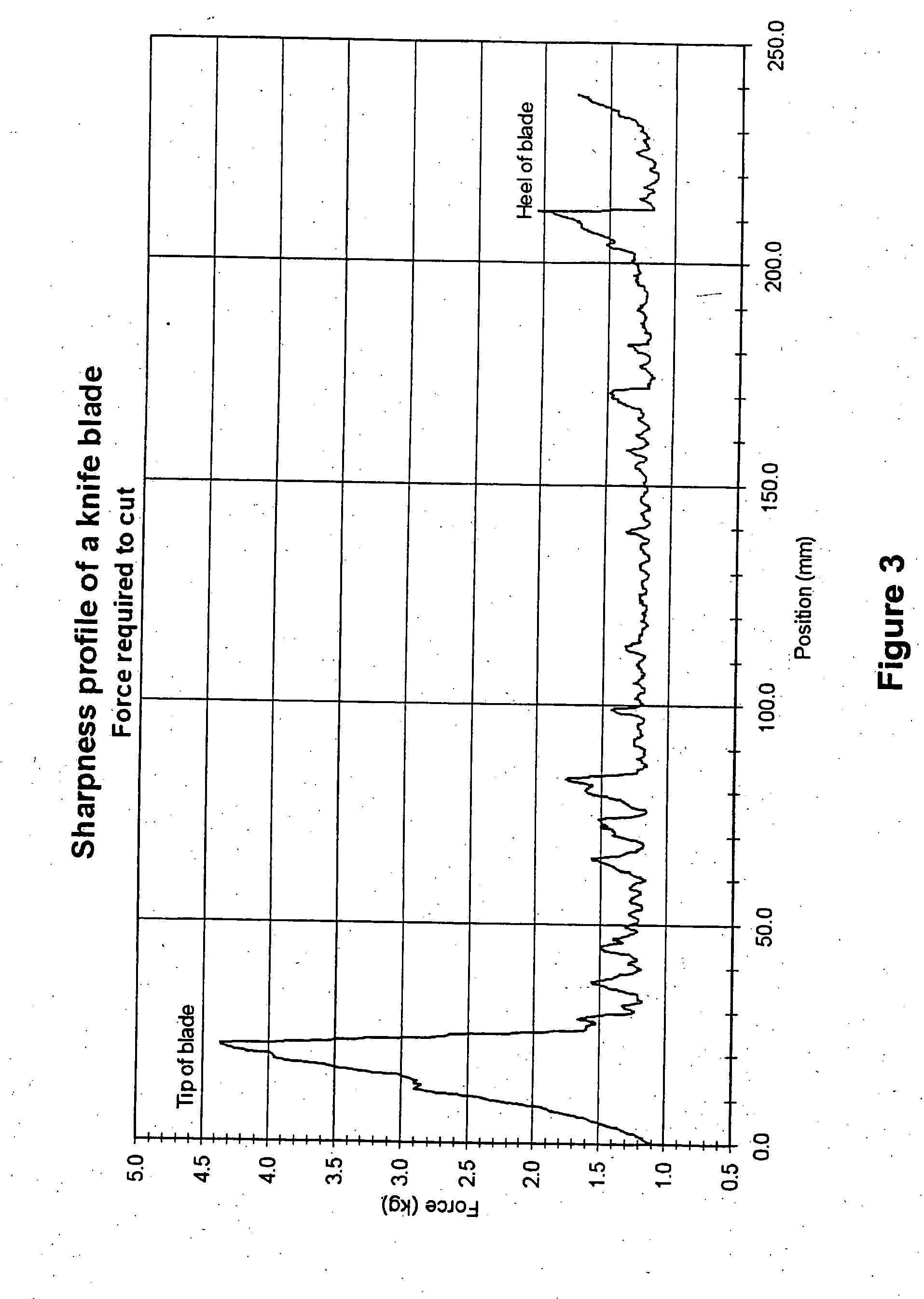
[0016]FIG. 3 is a sample plot of a graph showing a plot at distance v force for a blade tested in an embodiment of the sharpness tester according to the invention,

[0017]FIG. 4 is an illustration of a commercial form of the invention,

[0018]FIG. 5 is a more detailed illustration of the version shown in FIG. 4,

[0019]FIG. 6 is a block diagram of the electronic elements of the invention but for sharpness and roughness testing, and

[0020]FIG. 7 is a schematic illustration of the sharpness tester when used for roughness testing.

DETAILED DESCRIPTION OF A PREFERRED EMBODIMENT

[0021] In the form of the sharpness tester, which has currently ...


PUM

PropertyMeasurementUnit
force measuringaaaaaaaaaa
forceaaaaaaaaaa
linear distance measurementaaaaaaaaaa

Abstract

A sharpness tester for testing the sharpness of a blade. The tester has a blade holder 19 and a mounting arrangement 21, 22 for mounting a cuttable material 20. The blade holder 19 is mounted by a carriage 18 which is moveable on a track 14 so that the blade can move relative to the material 20 and contact the material. A linear distance measuring device and a force measuring device 21 enable the tester to determine the force required by part of the blade B to cut the material 20.

Description

BACKGROUND OF THE INVENTION [0001] This invention relates a sharpness tester. [0002] It is often desirable to be able to measure the cutting ability of a cutting edge such as that of a blade e.g. a butcher's or meat processor's knife. Currently there is no known method of directly, accurately, reliably, repeatably and non-destructively measuring the cutting ability of a blade. Current methods are either subjective and / or measure ability of a blade to retain its edge. These methods do not provide the ability to accurately locate blunt / sharp portions of a blade. SUMMARY OF THE INVENTION [0003] The object of the present invention is to provide a sharpness tester whereby an objective and quantifiable test of the sharpness of a blade along multiple parts of the blade can be achieved and in manner, which ensures damage to the edge, is minimal. [0004] Broadly according to one aspect the present invention provides a sharpness tester including a blade holder, a mounting arrangement for mount...

Claims


Application Information

Patent Timeline
Patent Type & Authority Applications(United States)
IPC IPC(8): G01N3/58G01B7/34
CPCG01N3/58
Inventor DOWD, PETER CHRISTOPHER
Owner DOWD PETER CHRISTOPHER
Learn More