Clutch for steer-by-wire steering system

a steering system and wire technology, applied in the direction of electrical steering, anti-theft devices, transportation and packaging, etc., can solve the problems of inability to do with that kind of electric motor without a gear, damage, etc., and achieve the effect of high load and relatively economical production of freewheels

Inactive Publication Date: 2006-09-14
ROBERT BOSCH GMBH 50 +1
View PDF21 Cites 8 Cited by
  • Summary
  • Abstract
  • Description
  • Claims
  • Application Information

AI Technical Summary

Benefits of technology

[0014] With the aid of the braking device acting on the steering column, the braking device being actuated as a function of the torque transmitted from the stator to the vehicle, it is possible in a simple way to assure that as needed, even major torques can be reported back from the steering column to the vehicle driver via the steering wheel. This can be the case for instance if the steering stop of the steer-by-wire steering system is reached, or if the vehicle with its steered wheels strikes a curb, and so forth. In all these situations, it suffices to exert a major braking moment on the steering column; there is no need for a rotary motion to be executed by the steering wheel actuator or the braking device. As a result, it is possible to dispense with the installation of a step-down gear in the steering wheel actuator, and this makes a very good steering feel with little moment fluctuation and low noise development possible.
[0015] In one embodiment of the steering system, it suffices to close the clutch, thus activating the mechanical fallback plane in order to make the steering wheel hard to move and giving the vehicle driver the feeling of a “stop”, or rotary angle limitation of the steering wheel.
[0018] By embodying the braking device as a switchable freewheel, it is attained that major braking moments can be transmitted to the steering column in the smallest possible space. Each of the clamping bodies individually engages the steering column linearly, and moreover, many clamping bodies are distributed over the circumference of the steering column, so that excessively high loads are not put on the steering column when the braking device is activated. Notch effects or the like no longer need be feared, either. Moreover, freewheels can be produced quite economically.
[0019] In a further feature of the invention, it is provided that the clamping bodies are guided in a cage; that the clamping bodies are pressed away from the first face by spring elements integrated with the cage, or by the cage itself; that the stator is supported so that it swings; that the cage and the stator are connected to one another in a manner fixed against relative rotation; that the rotor of the steering wheel actuator is connected to the first face in a manner fixed against relative rotation; and that the rotation of the stator relative to the outer race is prevented, by means of at least one spring element that acts on both the stator and the outer race, until the tripping moment is reached. In this embodiment, the steering wheel actuator is integrated with the braking device, and the torque transmitted by the steering wheel actuator to the steering column is used directly to actuate the braking device of the invention. This purely mechanical embodiment is quite sturdy and is intrinsically independent of any interference that might occur in the control unit and of the supply voltage to the on-board electrical system of the vehicle.

Problems solved by technology

If higher moments are to be simulated for the driver, for instance by means of a steering stop or curb stop of the wheels, however, this cannot be done with that kind of electric motor without a gear.
If the flat spiral spring is rotated excessively, it becomes damaged.

Method used


Image

  • Clutch for steer-by-wire steering system
  • Clutch for steer-by-wire steering system
  • Clutch for steer-by-wire steering system

Examples


Embodiment Construction

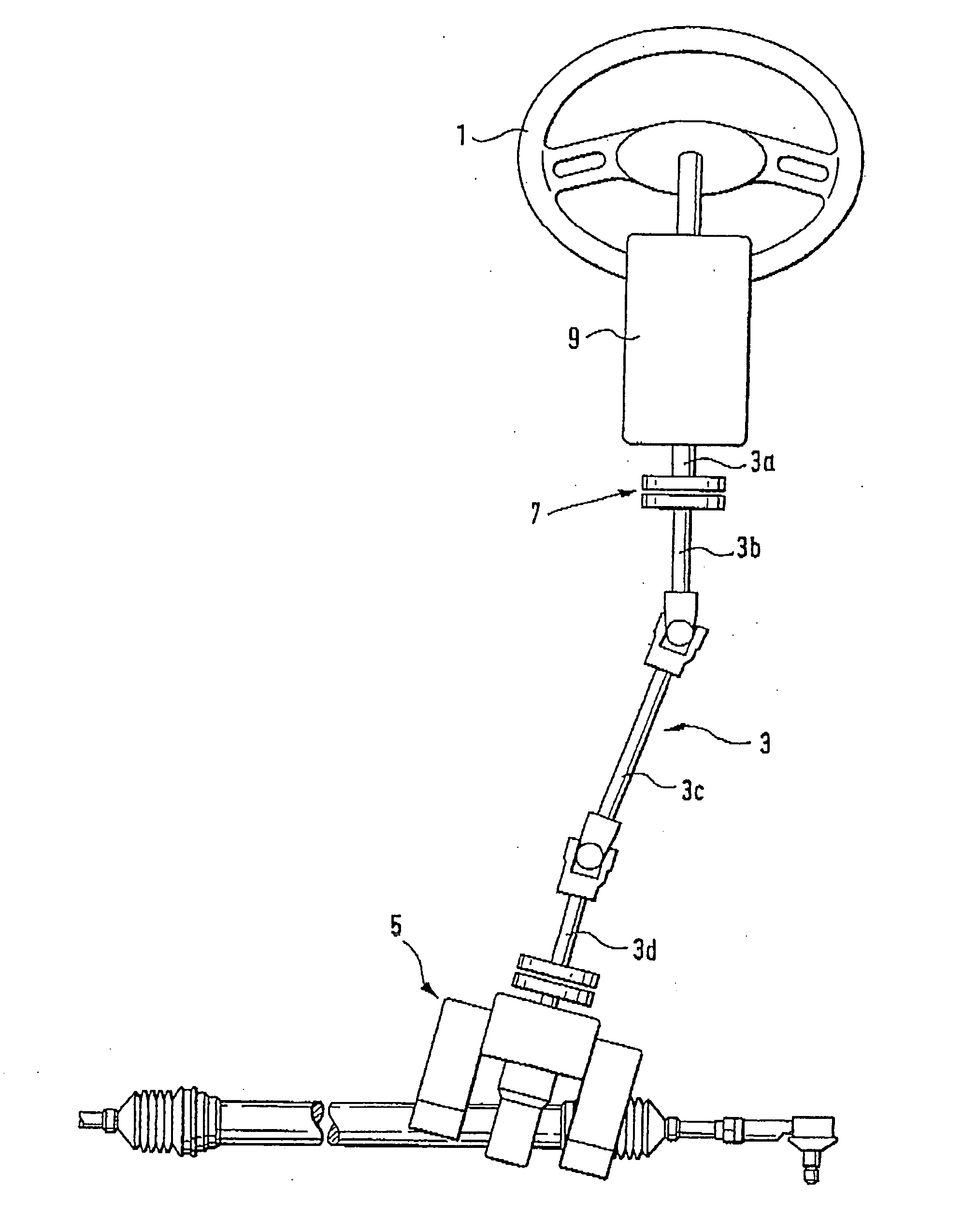
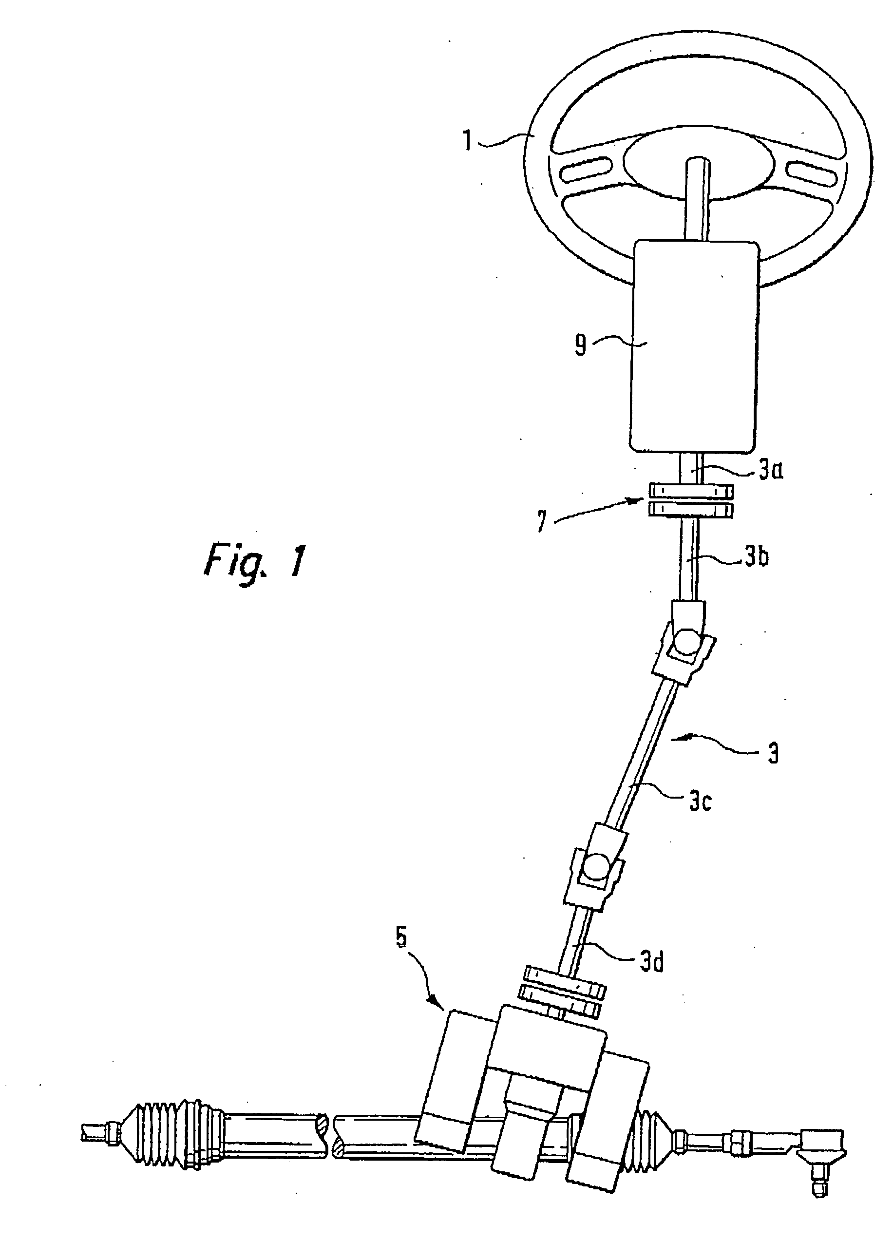
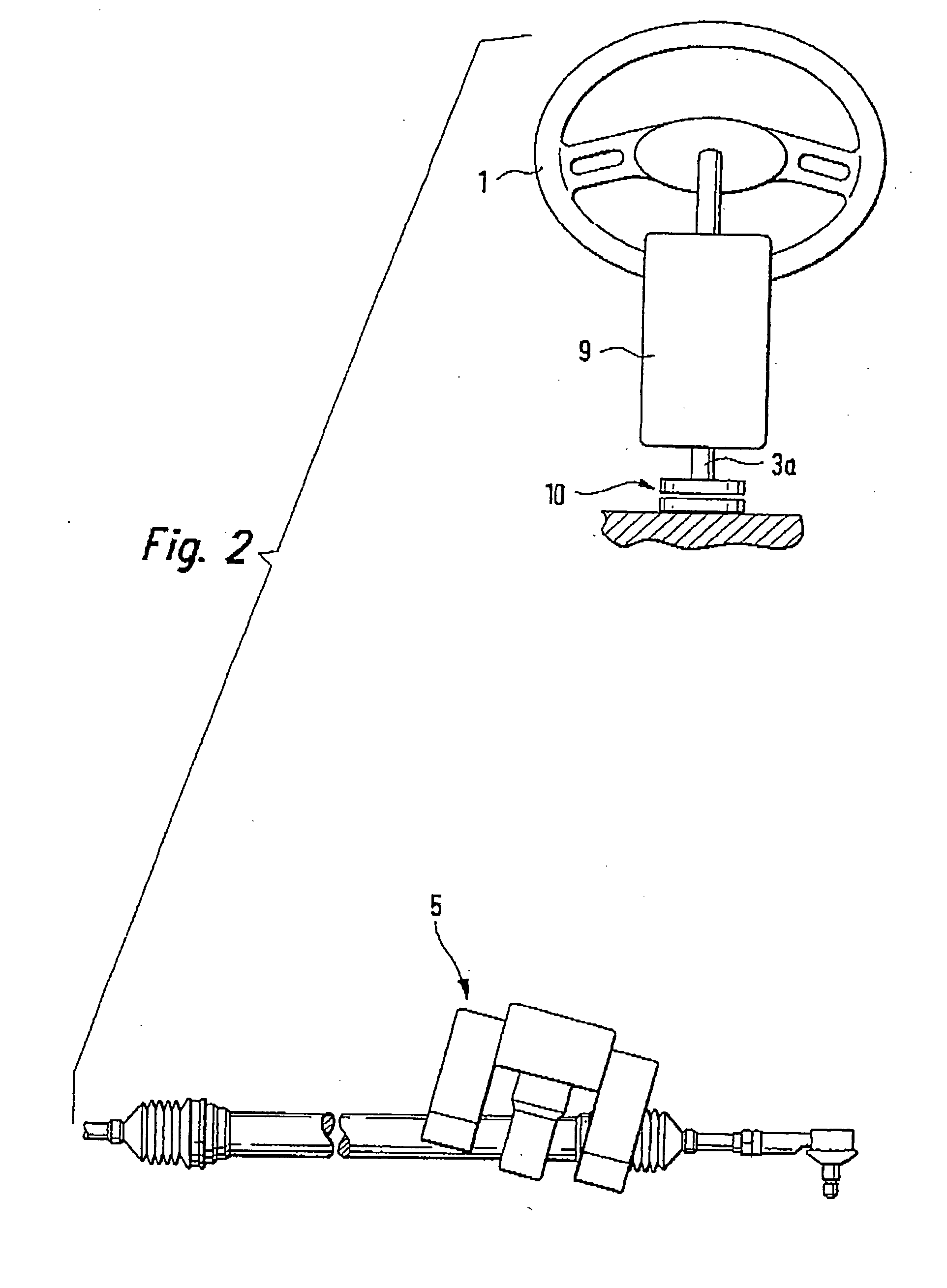
[0031] In FIG. 1, a steer-by-wire steering system with a mechanical fallback plane is shown schematically. The task of every steering system is for the steering wish, expressed by turning a steering wheel 1, to be transmitted to the steered wheels of the vehicle, which are not shown in FIG. 1. In conventional mechanical, hydraulic or electrical steering systems, this transmission is done via a steering column 3, which is composed of multiple parts 3a, 3b, 3c and 3d, and a steering actuator 5, as a rule embodied as a steering gear, which converts the rotary motion of the steering column 3 into a linear motion.

[0032] In a steer-by-wire steering system, the steering column 3 is divided by a clutch 7 between the parts 3a and 3b. It is understood that the clutch 7 can also be disposed at the parts 3c or 3d.

[0033] In the steer-by-wire mode, that is, with the clutch 7 open, the driver's steering wish is picked up at the part 3a of the steering column that is connected directly to the ste...


PUM


Abstract

A steer-by-wire steering system has a steering wheel actuator and a braking device that acts on the steering column. The braking device is activated when the vehicle steering wheel is to be blocked or at least sharply braked, such as when the steering stop is reached or a wheel goes over the edge of a curb. The braking device functions like a switchable freewheel.

Description

CROSS-REFERENCE TO RELATED APPLICATIONS [0001] This application is a divisional of application Ser. No. 10 / 181,625, which is a 35 USC 371 application of PCT / DE 01 / 04261 filed on Nov. 16, 2001.BACKGROUND OF THE INVENTION [0002] 1. Field of the Invention [0003] The invention relates to a steer-by-wire steering system for a vehicle, having a manual steering device, in particular a steering wheel, connected to a steering column, and having a steering wheel actuator acting on the steering column, the steering wheel actuator having a rotor, connected to the steering column in a manner fixed against relative rotation, and a stator. [0004] 2. Description of the Prior Art [0005] Steer-by-wire steering systems are distinguished in that in normal operation, there is no direct mechanical connection between the steering wheel and the steered wheels. Instead, the steering desired by the driver is detected via rotary angle sensors at the steering column and processed by a control unit, which trans...

Claims


Application Information

Patent Timeline
Patent Type & Authority Applications(United States)
IPC IPC(8): B62D5/00B60R25/021B62D1/16B62D5/04
CPCB60R25/0211B62D5/003B62D5/005B62D5/006
Inventor DOMINKE, PETERCAO, CHI-THUANPFEIFFER, WOLFGANGLEIMBACH, KLAUS-DIETERHARTER, WERNERHAFERMALZ, JENSKNOEDLER, HELMUTLEUTNER, WILFRIEDSCHUELE, JUERGENLOHNER, HERBERT
Owner ROBERT BOSCH GMBH 50
Why Eureka
Try Eureka