Workpiece support device

Inactive Publication Date: 2006-09-14
KOGANEI
6 Cites 12 Cited by

AI-Extracted Technical Summary

Problems solved by technology

According to the technique disclosed in Patent Document 1, since the rod is moved upward or downward by moving horizontally the wedge-shaped block, a space for moving the wedge-shaped block is necessary for being ensured in the horizontal direction, which results in an increase of size of the workpiece support device.
Therefore, it is diffic...

Benefits of technology

[0013] According to the present invention, when a plurality of workpiece support devices are combined, the workpiece can be supported at multiple points by the plurality of support rods. By adjusting the projection amounts of the respective support rods, even a workpiece with a non-flat abutment face or a thin, easily deformable workpiece can be supported stably by the plurality of support rods. Further, by placing the workpiece at the tip portion of the s...

Abstract

A projection amount of rod can be adjusted, and workpiece with various shapes or easily deformable workpiece can be stably supported. When an opening/closing valve is switched to an opening position and a working medium flows and is injected from one medium chamber to another medium chamber, a support rod moves upward until an upper face of a first piston abuts on a cover member. Next, when the workpiece is placed on the support rod, the support rod is pushed down. When the workpiece moves downward to a predetermined height, the working medium is prevented from flowing between one medium chamber and another medium chamber if the opening/closing valve is switched to the closing position. Therefore, movement of the support rod is stopped. Since the working medium is sealed in the workpiece support device, it does not leak to the outside.

Application Domain

Large fixed membersPositioning apparatus +4

Technology Topic

PistonMechanical engineering

Image

  • Workpiece support device
  • Workpiece support device
  • Workpiece support device

Examples

  • Experimental program(1)

Example

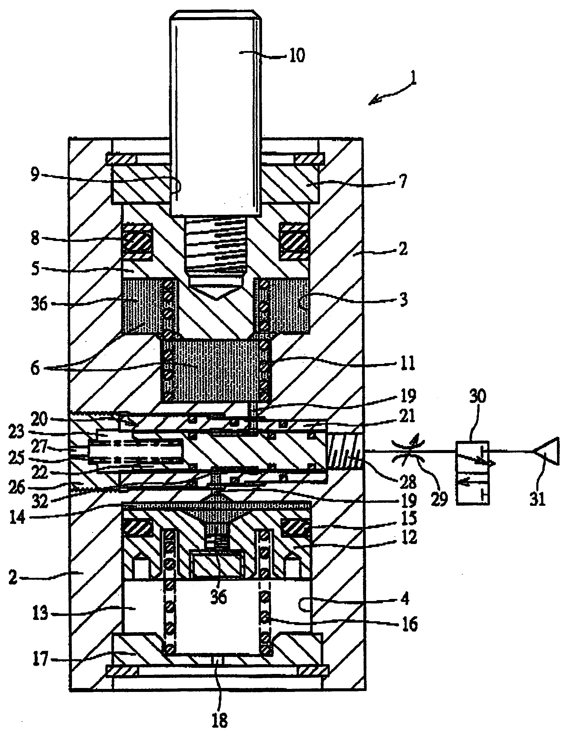
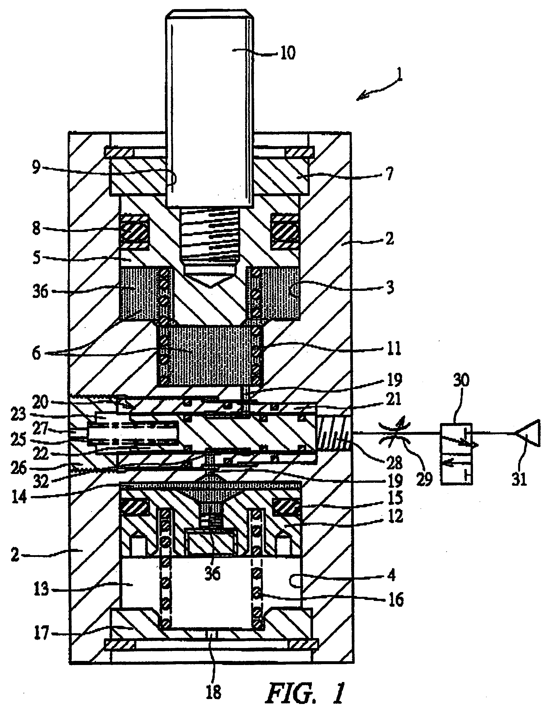
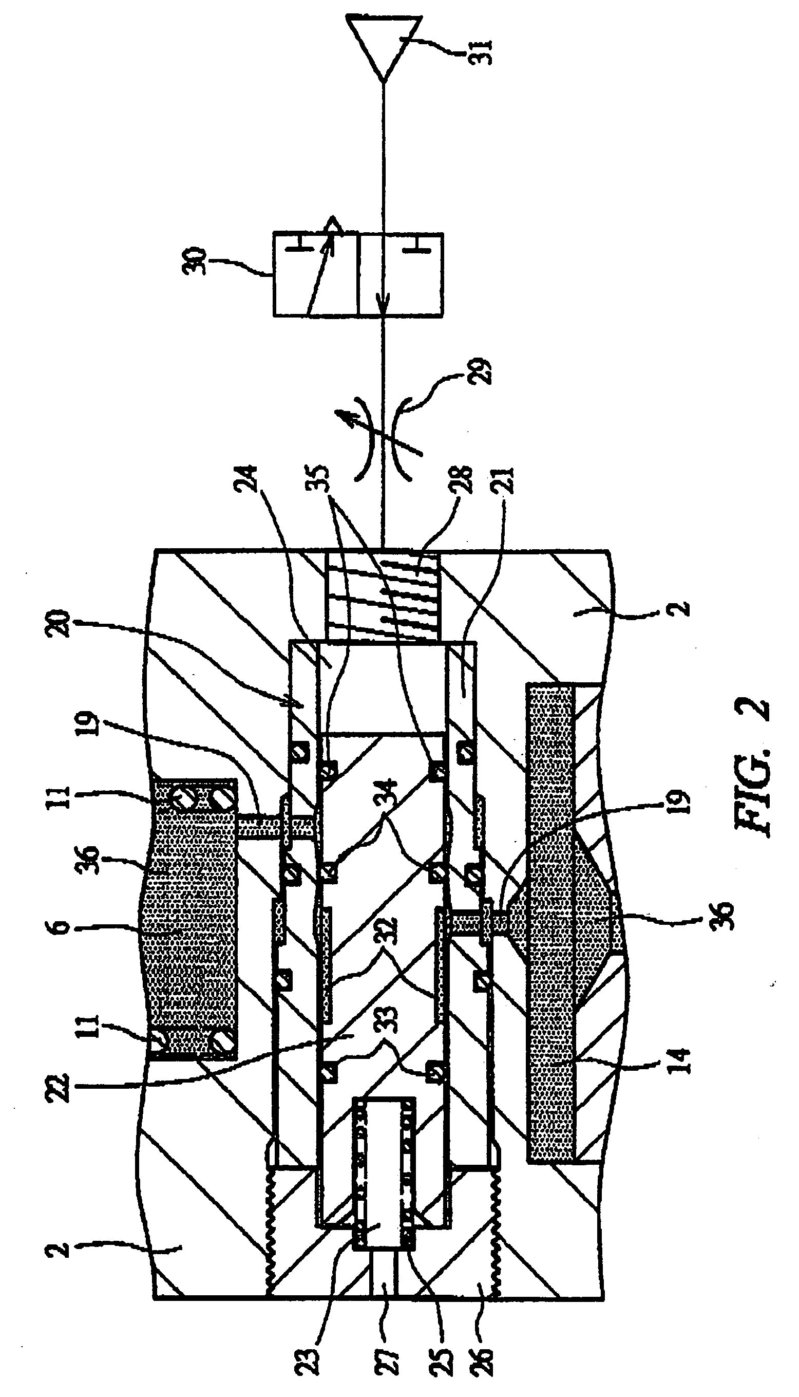
[0019]FIG. 1 is a sectional view showing a workpiece support device according to an embodiment of the present invention, and FIG. 2 is an enlarged view showing a state where a third piston shown in FIG. 1 has been moved at a closing position.
[0020] A workpiece support device 1 has a support stand 2 with a cubic shape, a first cylinder chamber 3 is partitioned and formed at an upper portion of the support stand 2, and a second cylinder chamber 4 is partitioned and formed at a lower portion of the support stand 2.
[0021] A first piston 5 is accommodated in the first cylinder chamber 3 so as to be reciprocable vertically, and a first medium chamber 6 serves as a lower end face side of the first piston 5. A bottom face of a cover member 7 fitted for partitioning and forming the first cylinder chamber 3 serves as a stopper face of the first piston 5 for reciprocation and, as shown in FIG. 1, a position where the first piston 5 abuts on the stopper face is set as an advance limit position of the first piston 5. A sealing member 8 is fitted on the first piston 5 so that communication between the first medium chamber 6 and the outside is blocked.
[0022] A through hole 9 is formed in the cover member 7, a support rod 10 is incorporated in the through hole 9 so as to be reciprocable vertically, and a base end portion of the support rod 10 is fixed to the first piston 5, so that the support rod 10 also reciprocates integrally with reciprocation of the first piston 5. A tip portion of the support rod 10 abuts on a lower side of an unshown workpiece to support the workpiece on the lower side.
[0023] A first pressing member 11, which presses the first piston 5 in a direction of making the tip portion of the support rod 10 project from the support stand 2, is incorporated in the medium chamber 6, and the first pressing member 11 illustrated serves as a compression coil spring, whereby the first piston 5 is such that a pressing force is always biased in a direction of making the support rod 10 project.
[0024] A second piston 12 is reciprocably accommodated in the second cylinder chamber 4, and the second piston 12 constitutes a piston pair along with the first piston 5. A spring chamber 13 is located on a lower end face side of the second piston 12, and a medium chamber 14 is located on an upper face side of the second piston 12. A seal member 15 is fitted on the second piston 12 similarly to the first piston 5, so that communication between the spring chamber 13 and the medium chamber 14 is blocked. A second pressing member 16, which presses the second piston 12 in a direction of reducing a volume of the medium chamber 14, is incorporated in the spring chamber 13. The second pressing member 16 illustrated is a compression coil spring similarly to the first pressing member 11, and the second piston 12 is always biased in a direction of reducing a volume of the medium chamber 14. A cover member 17, which partitions and forms the second cylinder chamber 4 and supports the second pressing member 16, is fitted into the support stand 2, and a bleed hole 18 is formed in the cover member 17.
[0025] A communication path 19, by which the first medium chamber 6 communicates with the second medium chamber 14 pairing with the first medium chamber 6, is formed in the support stand 2, and an opening/closing value 20 for opening and closing the communication path 19 is further incorporated into the support stand 2. The opening/closing valve 20 is a spool valve having: a sleeve 21 fitted into an attaching hole formed in the support stand 2 so as to cross the communication hole 19; and a spool 22 disposed in a valve accommodating hole of the sleeve 21 so as to be reciprocable axially, wherein the spool 22 can be switched between two positions of an opening position where the two medium chambers 6 and 14 forming a pair are caused to communicate with each other and a closing position where a state of communicating with both medium chambers is blocked. A spring chamber 23 is partitioned and formed on one end face side of the spool 22 and, as shown in FIG. 2, a pressure chamber 24 is partitioned and formed on the other end face side thereof.
[0026] As illustrated, a pressing member 25 which presses the spool 22 in a direction of moving the spool 22 at the opening position is incorporated into the spring chamber 23. The pressing member 25 is a compression coil spring like the first and second pressing members 11 and 16, and the spool 22 is always biased in a direction of moving the spool 22 to the opening position by the pressing member 25. A cover member 26, which partitions and forms the spring chamber 23 and abuts on an end face of the spool 22, is fitted into the support stand 2 and a bleed hole 27 is formed in the cover member 26.
[0027] A switching port 28 is formed in the pressure chamber 24, and an air pressure source 31 is connected to the switching port 28 via a variable throttle 29 and a switching valve 30. The switching valve 30 can be switched between two positions of a supplying position where compressed air is supplied to the switching port 28 and a supply stopping position where supply of compressed air is stopped and the compression chamber 24 is released to the atmosphere. Therefore, when the switching value 30 is moved at the supplying position, the compressed air is supplied to the compression chamber 24, so that the spool 22 is moved to the closing position against a biasing force of the pressing member 25. On the other hand, when the switching valve 30 is moved at the supply stopping position, the spool 22 is moved to the opening position by a pressing force of the pressing member 25, so that the compressed air in the pressure chamber 24 is discharged to the outside.
[0028] A communication groove 32 for ensuring a state of communicating with the communication path 19 at a time of being at the opening position is formed along an outer circumferential face of the spool 22. Seal members 33 and 34 for blocking communication with the communication groove 32 and the spring chamber 23 and that with the communication groove 32 and the pressure chamber 24 are respectively fitted on both sides of the communication groove 32, and a seal member 35 for blocking communication between the communication path 19 and the pressure chamber 24 at a time of being at the closing position is fitted at an end portion of the spool 22.
[0029] Thus, non-compressible working media 36 are sealed in the first medium chamber 6, the second medium chamber 14, and the communication path 19 which are put in a state of being blocked from communication with the outside by the seal members 33 to 35. Liquid such as oil is used as the working media 36. Since the working media 36 is sealed in the respective medium chambers 6 and 14 via the communication paths 19, when an external force is, for example, applied to the support rod 10 so that the support rod 10 retracts and the first piston 5 is moved downward to reduce a volume of the medium chamber 6, the working medium corresponding to a reduction amount of the volume flows in the medium chamber 14 to press the second piston 12 and increase a volume of the medium chamber 14. Further, when the external force acting in the direction of retracting the support rod 10 is not applied, a pressing force acting in a direction of making the support rod 10 project is applied to the support rod 10 by the first pressing member 11, and a pressing force acting in the direction of making the support rod 10 project is applied to the support rod 10 via the second piston 12 and the working medium 36 by the second pressing member 16. Therefore, the support rod 10 is advanced in a direction of projecting to the outside of the support stand 2 by the pressing forces. At this time, the working medium 36 inside the second medium chamber 14 flows in the first medium chamber 6. That is, the first and second pistons 5 and 12 forming a pair are moved axially in synchronization with each other by the working medium. Note that even if one of the two pressing members 11 and 16 serving as pressing means is removed, an advance-directional pressing force can be applied to the support rod 10. In addition, by using the spring chamber 13 as a pressure chamber to supply or seal compressed air thereto or therein, compressible fluid such as air is used as pressing means.
[0030] Next, an operation of the workpiece support device 1 will be described. When the switching valve 30 is first switched to the stopping position before the workpiece is placed, the compressed air is not supplied to the compression chamber 24 and the spool 22 is switched to the opening position, so that the two medium chambers 6 and 14 forming a pair communicates with each other via the communication path 19. Thereby, the working media 36 can flow in the two medium chambers 6 and 14, and the support rod 10 is advanced by the two pressing members 11 and 16 until the first piston 5 abuts on the cover member 7, and the working medium 36 flows from the medium chamber 14 to the medium chamber 6. At this time, the working media 36 are prevented from flowing to the outside by the seal members 8, 15, and 33 to 35.
[0031] When the unshown workpiece is placed on a tip of the support rod 10, the weight of the workpiece itself acts on the support rod 10 in a direction of being against the two pressing members 11 and 16, so that the support rod 10 is pushed down by flowing-in of the working medium 36 from the medium chamber 6 to the medium chamber 14. At this time, if path cross-sectional areas of the communication path 19 and the communication groove 32 are set small, a flow rate per unit time of the working medium 36 is also small, whereby the support rod 10 can be pushed down gradually.
[0032] When the support rod 10 is pushed down to a predetermined position, the switching valve 30 is switched to the supplying position (see FIG. 2). Accordingly, the compressed air is supplied to the pressure chamber 24, and the spool 22 is switched to the closing position, so that the communication path 19 is closed and the communication between the two medium chambers 6 and 14 is blocked. Thereby, the working medium 36 cannot flow between the two medium chambers 6 and 14, and movement of the support rod 10 is stopped. At this time, the working medium 36 is prevented from flowing to the outside by the seal members 8, 15, and 33 to 35. Thus, since the switching valve 30 is switched to the supplying position at predetermined timing, the workpiece can be held at predetermined height. After a predetermined working such as a processing or inspecting working performed to the workpiece is completed, when the workpiece is removed from the support rod 10 and the switching valve 30 is switched to the closing position, the working medium 36 can flow between the two medium chambers 6 and 14, whereby the first piston 5 and the support rod 10 can be moved upward to the respective advance limit positions.
[0033]FIG. 3 is a perspective view showing a workpiece support device according to one embodiment of the present invention, and FIG. 4 is a sectional view taken along line A-A shown in FIG. 3. Note that, in FIGS. 3 and 4, the same members as those shown in FIG. 1 are denoted by the same reference numerals and repetitive explanation thereof will be omitted.
[0034] A workpiece support device 37 shown in FIG. 3 is constituted by using the workpiece support device 1 shown in FIG. 1 as one unit 1a and combining a plurality of units 1a, and these units are disposed on a base stand plate 38. A total of twelve units 1a are disposed on the base stand plate 38 in a matrix manner of three rows×four columns. Accordingly, in the workpiece support device 37, twelve piston pairs each including the first piston 5 and the second piston 12 are provided, twelve pairs each including the first and second medium chambers 6 and 14 forming a pair are provided, the working media 36 are sealed in the respective medium chambers 6 and 14 independently, and twelve opening/closing valves 20 are provided so as to correspond to twelve communication paths 19.
[0035] The number of units 1a disposed on the base stand plate 38 is shown as one example of the workpiece support device 37, and any number of units 1a can be disposed on the base stand plate 38 in accordance with shape or the like of a workpiece W to be supported. Accordingly, by changing the number of units 1a having approximately the same structure as those of the workpiece support devices 1 to be combined, the workpiece support device 37 with various sizes can be assembled so as to support a workpiece with any size. Incidentally, for example, there may be adopted such a constitution that one block member with a size corresponding to the support stands 2 having the same number as that of units shown in FIG. 3 is used as a common support stand and that the support rods 10, the pistons 5 and 12, and the like which constitute the number of corresponding units 1a are assembled in the one block member. Or, there may be adopted a constitution in which a portion corresponding to the base stand plate 38 is integrally formed on the block member.
[0036] Each unit 1a in the workpiece support device 37 has the same structure as that of the workpiece support device 1 shown in FIGS. 1 and 2 except that a communication flow path 39 extending from the switching portion 28 toward the base stand plate 38 and being opened at a bottom face of the unit is formed. As shown in FIG. 3, a common flow path 40 opened at a side face of the base stand plate 38, and branch flow paths 41 branched from the common flow path 40 and connected respectively to the communication flow paths 39 are formed in the base stand plate 38, and a common port 42 is formed at one end of the common flow path 40. An air pressure source 31 is connected to the common port 42 via a variable throttle 29 and a switching valve 30, so that by opening the switching valve 30 and supplying the compressed air to the common port 42, the compressed air can be simultaneously supplied to respective compression chambers 24 via the common flow path 40 and the communication flow paths 39. Thus, in the workpiece support device 37 shown in FIGS. 3 and 4, all the opening/closing valves 20 can be operated simultaneously by the one switching valve 30. Note that the other end of the common flow path 40 is sealed by an unshown closing member.
[0037] In such a workpiece support device 37, various workpieces W can be supported stably by using a plurality of support rods 10. For example, even if the lower face of the workpiece W, i.e., an abutment face thereof on which the support rods 10 abut changes stepwisely in a portion extending along the line A-A, the workpiece W can be supported in such a stable manner that an upper face of the workpiece is kept horizontally by adjusting the respective projection amounts of support rods 10. That is, when the switching valve 30 is switched to the stopping position before the workpiece W is placed on the support rods 10, like the workpiece support device 1 shown in FIG. 1, the compressed air is not supplied to the pressure chambers 24 of the individual units 1a and all the twelve spools 22 are switched to the opening positions, so that the respective medium chambers 6 and 14 forming pairs communicate with each other via the communication path 19. Thereby, the working medium 36 flows and is injected from the medium chamber 14 to the respective medium chambers 6, so that the respective support rods 10 project upward to the advance limit positions where the upper faces of the first pistons 5 abut on the respective cover members 7.
[0038] Next, when the workpiece W is placed on the tip portions of the support rods 10, the weight of the workpiece itself acts on the support rods 10, so that the respective support rods 10 are pushed down gradually. At this time, the respective support rods 10 are pushed down so as to correspond to the thickness of portions of the workpiece W abutting on the support rods 10. Note that when the workpiece W is placed, the workpiece W may be pushed to the support rods 10 so that a surface of the workpiece becomes horizontal.
[0039] As shown in FIG. 4, when the workpiece W moves downward to the predetermined height under such a state that the tip portions of all the support rods 10 abut on the workpiece W, the switching valve 30 is switched to the supplying position. Thereby, the working medium 36 cannot flow between the medium chamber 6 and the medium chamber 14 forming a pair, and movement of the respective support rods 10 is stopped, so that the workpiece W can be supported stably by using the plurality of support rods 10.
[0040] After the predetermined working performed to the workpiece W is completed, when the workpiece W is removed from the support rods 10 and the switching valve 30 is switched to the closing position, the first positions 5 and the support rods 10 can be moved upward to the advance limit positions, respectively.
[0041] The present invention is not limited to the above embodiments and, needless to say, may be variously modified and altered within the scope of not departing from the gist of the invention. For example, a switching operation of the spool 22 may be performed by using hydraulic pressure instead of compressed air. In the above embodiments, the second piston 12 is accommodated so as to be reciprocable vertically, but may be accommodated so as to be reciprocable horizontally. On the other hand, the spool 22 is accommodated so as to be reciprocable horizontally, but may be accommodated so as to be reciprocable vertically.
[0042] In the above embodiments, the pressing member 25 is incorporated in the spring chamber 23, but the spool 22 may be pressed by supplying compressed air into the spring chamber 23. At this time, a pressing member such as a coil spring may be incorporated into the pressure chamber 24. Additionally, the spool 22 may be reciprocable by supplying negative pressure to the spring chamber.

PUM

no PUM

Description & Claims & Application Information

We can also present the details of the Description, Claims and Application information to help users get a comprehensive understanding of the technical details of the patent, such as background art, summary of invention, brief description of drawings, description of embodiments, and other original content. On the other hand, users can also determine the specific scope of protection of the technology through the list of claims; as well as understand the changes in the life cycle of the technology with the presentation of the patent timeline. Login to view more.

Similar technology patents

Closed wound drainage system

InactiveUS20050261643A1easily deformableproblem be solve
Owner:CONVATEC LTD

Fabric composite support or enclosure for an automotive battery pack

ActiveUS20120251863A1enhanced stiffnesseasily deformable
Owner:GM GLOBAL TECH OPERATIONS LLC

Decurling mechanism

ActiveUS20090190985A1easily deformablehigh effect
Owner:NORITSU PRECISION CO LTD

Manufacturing method of honeycomb structure

InactiveUS20180169896A1easily deformable
Owner:NGK INSULATORS LTD

Classification and recommendation of technical efficacy words

  • easily deformable

Closed wound drainage system

InactiveUS20050261643A1easily deformableproblem be solve
Owner:CONVATEC LTD

Fabric composite support or enclosure for an automotive battery pack

ActiveUS20120251863A1enhanced stiffnesseasily deformable
Owner:GM GLOBAL TECH OPERATIONS LLC

Decurling mechanism

ActiveUS20090190985A1easily deformablehigh effect
Owner:NORITSU PRECISION CO LTD

Manufacturing method of honeycomb structure

InactiveUS20180169896A1easily deformable
Owner:NGK INSULATORS LTD
Why Eureka
Try Eureka