Bellows for a joint arrangement, comprising a receiver for a retainer ring

a joint arrangement and receiver technology, applied in the direction of yielding couplings, engine seals, engine components, etc., can solve the problem of greater damage during operation

Inactive Publication Date: 2010-03-18
GKN DRIVELINE INT GMBH
View PDF5 Cites 0 Cited by
  • Summary
  • Abstract
  • Description
  • Claims
  • Application Information

AI Technical Summary

Problems solved by technology

Putting the retaining ring in place, however, is problematic precisely in relation to series production since a very high accuracy of fit and precisely aligned position of the retaining ring must be assumed before the retaining ri...

Method used


Image

  • Bellows for a joint arrangement, comprising a receiver for a retainer ring
  • Bellows for a joint arrangement, comprising a receiver for a retainer ring
  • Bellows for a joint arrangement, comprising a receiver for a retainer ring

Examples


Embodiment Construction

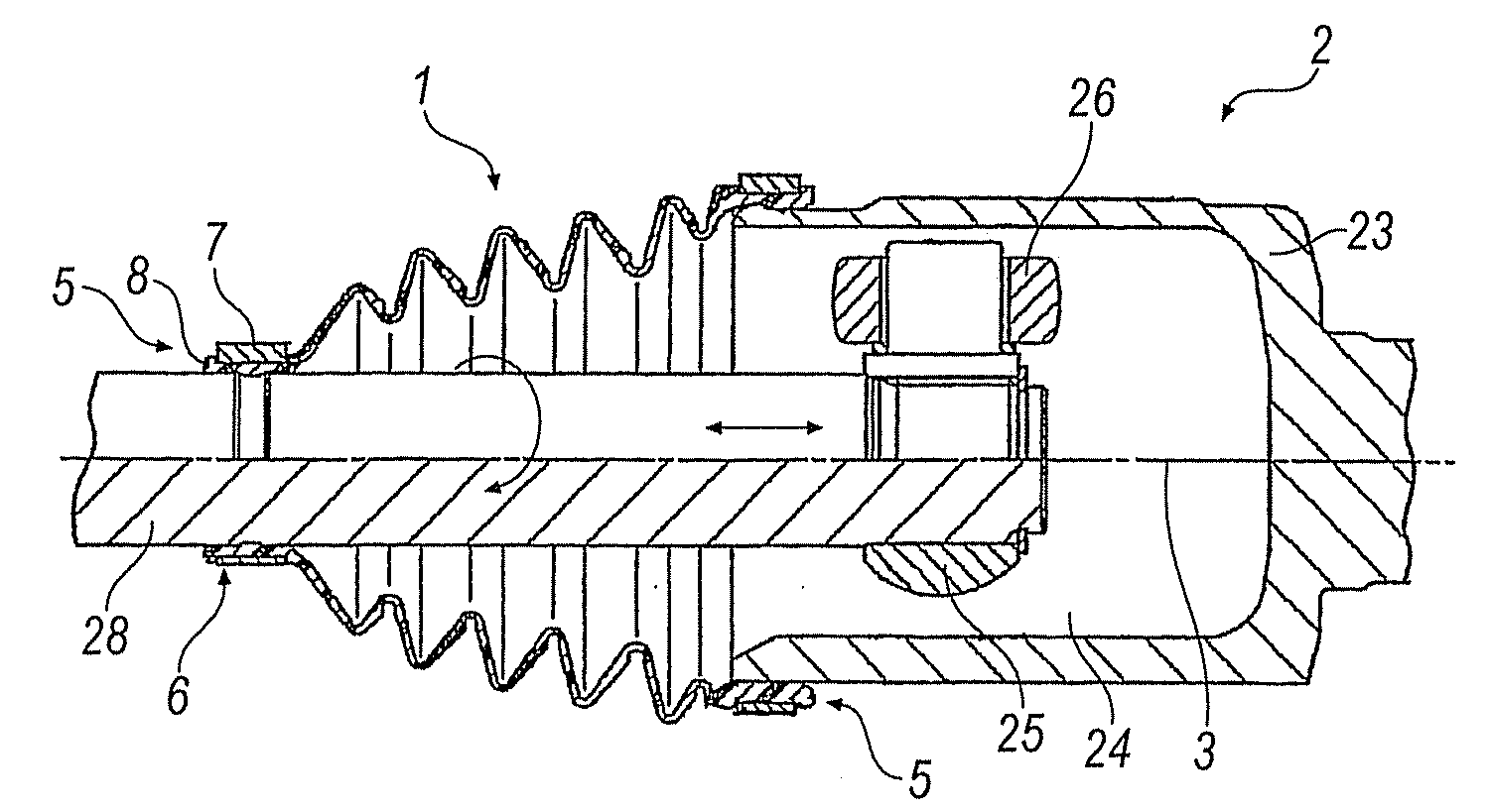
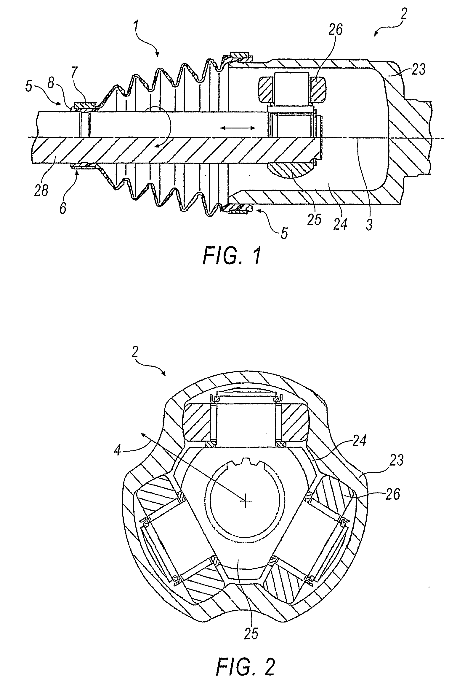
[0034]FIG. 1 schematically illustrates in partial cross-section, a possible embodiment variant of a joint arrangement 2 with a bellows 1 which collectively span a region from a shaft 28 to a joint outer part 23. In this case, bellows 1 is embodied on both ends 5 with a receiver 6 in which a retaining ring 7 is positioned. The receiver 6 ensures connection of the bellows 1 to shaft 28 or to joint outer part 23. It is also illustrated here that material elevations 8 are provided at end 5 that serves to join to shaft 28, which therefore forms the smaller opening cross-section.

[0035]Joint arrangement 2 is used to transmit a torque, wherein shaft 28 rotates. This rotational movement is transmitted via joint inner part 25 fastened on shaft 28. There, a plurality of rollers 26 which adjoin in joint outer part 23 are provided in the direction of radius 4 (cf. also FIG. 2). In order to ensure a bending angle between shaft 28 and joint outer part 23 and / or to ensure an axial relative movement...


PUM


Abstract

A bellows for a joint arrangement is disclosed. The bellows comprises an axis, a radius and two ends, a receiver for a retaining ring being formed in the zone adjacent to an end. The receiver is delimited by a plurality of elevations on the end which have a narrow cross-section in the direction of the radius and different flexural properties in opposite directions of the axis.

Description

CROSS-REFERENCE TO RELATED APPLICATIONS[0001]This application is a National Stage application which claims the benefit of International Application No. PCT / EP2006 / 009482 filed Sep. 29, 2006 which is hereby incorporated by reference in its entirety.BACKGROUND[0002]The present disclosure relates to a bellows for a joint arrangement, comprising an axis, a radius and two ends, a receiver for a retaining ring. The receiver is formed in a region adjacent to an end.[0003]Bellows are used in automobile manufacture to bridge a transition region from a shaft, which transmits a torque, to a joint outer part. Bellows further create a possibility, for example, of arranging lubricant in the joint region, as well as preventing dust or the like penetrating into the joint.[0004]The bellows, which are typically manufactured from a thermoplastic material, often have a conical shape. This conical shape is caused by ends of varying size since a generally smaller opening that is positioned on one end enc...

Claims


Application Information

Patent Timeline
IPC IPC(8): F16D3/16F16J15/52
CPCF16D3/2055F16J3/042F16D3/845
Inventor SCHOLTZ, THORSTENDEISINGER, MARKUSSCHMIDT, THOMAS
Owner GKN DRIVELINE INT GMBH
Why Eureka
Try Eureka