Pressure indicating structure

Active Publication Date: 2006-06-29
3M INNOVATIVE PROPERTIES CO
View PDF8 Cites 3 Cited by
  • Summary
  • Abstract
  • Description
  • Claims
  • Application Information

AI Technical Summary

Benefits of technology

[0007] The deformable layer can be formed entirely of pressure sensitive adhesive, or, to afford deformability of the deformable layer at a lower or higher predetermined pressure than is provided only by the use of a s

Problems solved by technology

The pressure required to develop full bond strength of that large area of pressure sensitive adhesive can be applied by sequentially pressing on top, bottom and side portions of the base plate, however, the person applying such pressure is never quite sure that enough pressure has been applied to each of those portions.
For example, the bottom and side portions may have had a sufficient amount of press

Method used


Image

  • Pressure indicating structure
  • Pressure indicating structure
  • Pressure indicating structure

Examples


first embodiment

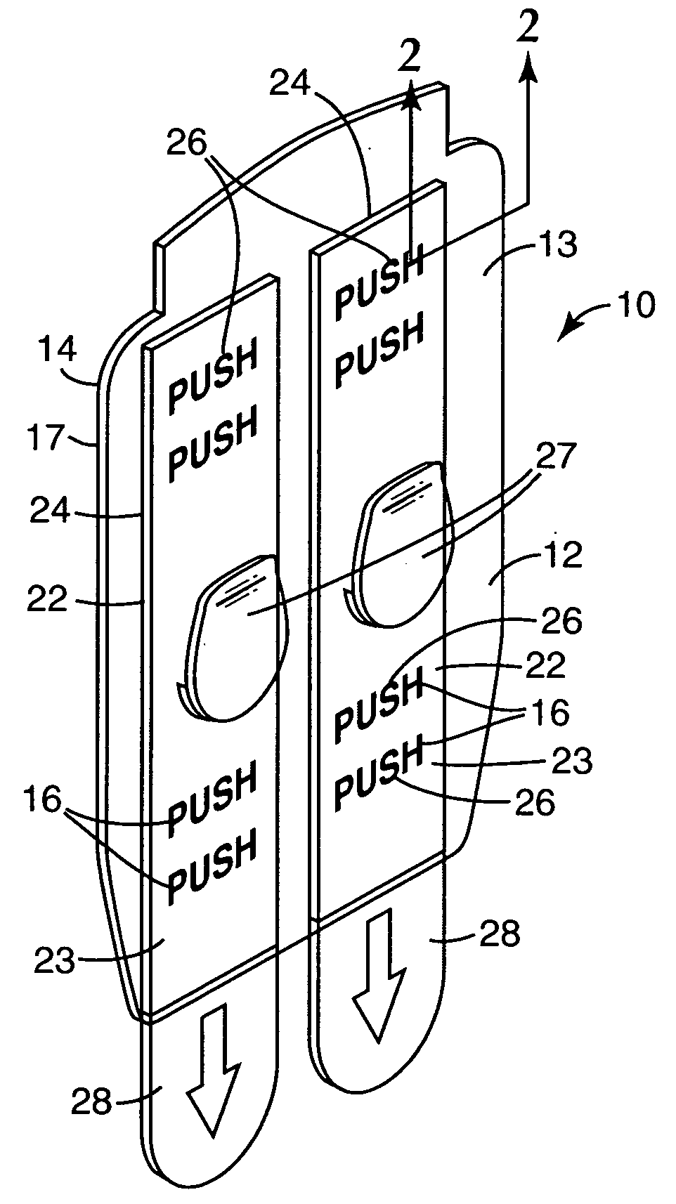
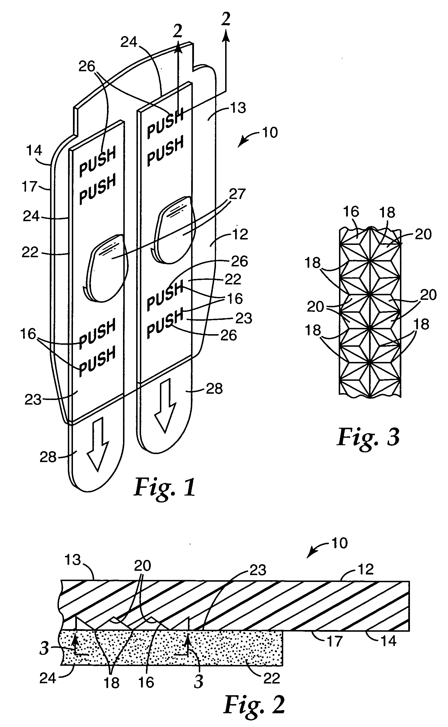
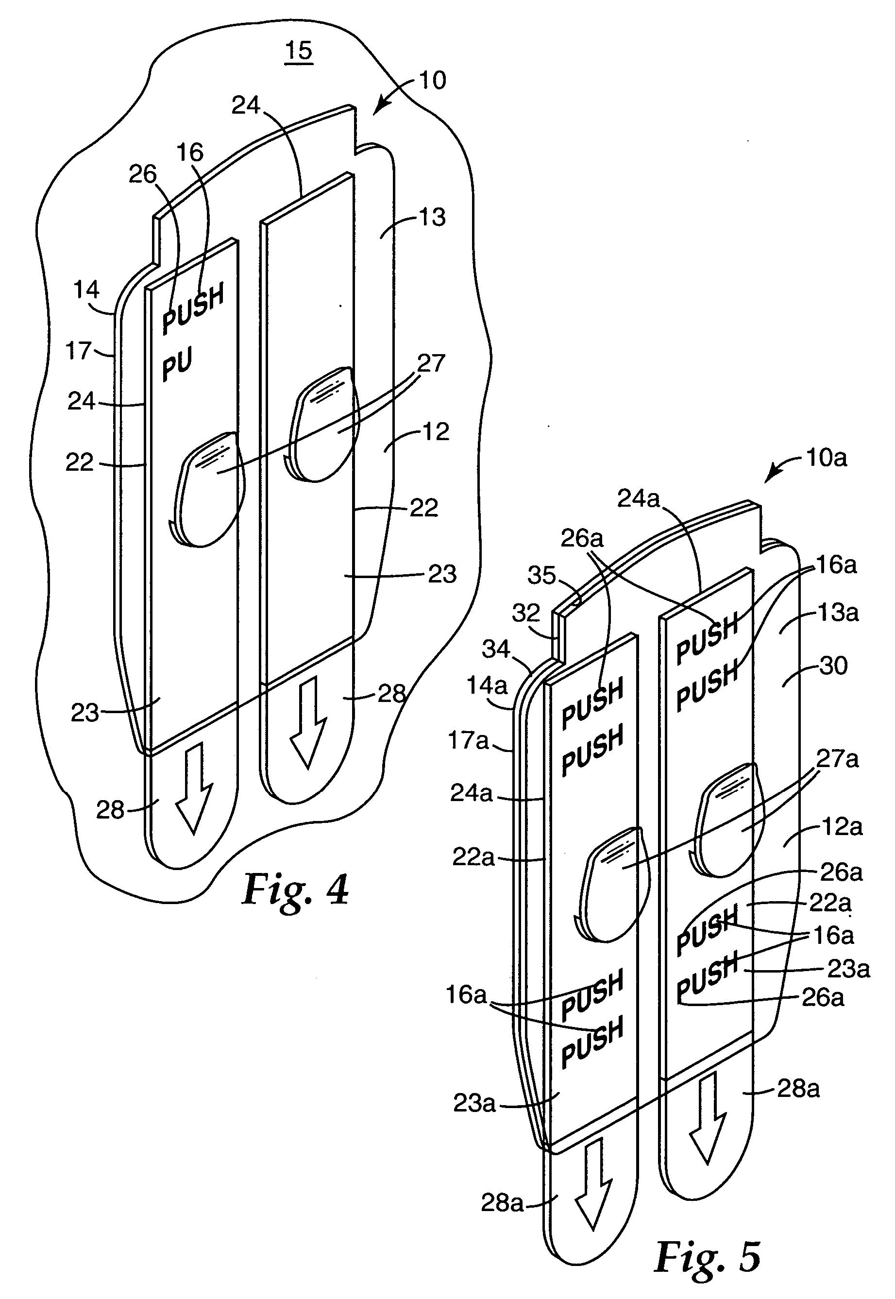
[0029] Referring now to FIGS. 1 through 4 of the drawing there is illustrated a pressure indicating structure 10 according to the present invention that can be releasably adhered to a surface 15 (see FIG. 4).

[0030] Generally, the pressure indicating structure 10 comprises a translucent or transparent polymeric sheet or plate 12 having opposite first and second major surfaces 13 and 14. A portion 17 of the second major surface 14 of the plate 12 is planar. The plate 12 has reflective structure 16 defining non-planar portions of its second surface 14, which reflective structure 16 is in the shape of indicia 26 (i.e., the words “PUSH” as illustrated). The reflective structure 16 reflects back through the first surface 13 at an observation angle in a predetermined range of angles with respect to the first surface 13 (e.g., at an observation angle in the range of about 60 to 90 degrees with respect to that first surface 13) a visually significant amount of the light entering the plate 12...

third embodiment

[0041] Referring now to FIGS. 6 through 8 of the drawing there is illustrated a pressure indicating structure according to the present invention generally indicated by the reference numeral 40.

[0042] Generally, the pressure indicating structure 40 comprises (1) a stiff but flexible translucent or transparent sheet 42 having opposite first and second major surfaces 43 and 44, reflective structure 46 defining the second surface 44 of the plate 42 for reflecting back through the first surface 43 at an observation angle in a predetermined range of observation angles (e.g., 60 to 90 degrees) with respect to the first surface 43 a visually significant amount of the light entering the plate 42 through its first surface 43. The reflective structure 46 (see FIG. 7) comprises a multiplicity of parallel elongate peak portions 48 and recessed portions having recessed surface portions 50 of the second surface 44 defining recesses from the peak portions; and (2) a deformable layer 52 comprising p...

fourth embodiment

[0048]FIGS. 9 and 10 illustrate a pressure indicating structure according to the present invention generally indicated by the reference numeral 60.

[0049] Generally, the pressure indicating structure 60 comprises a translucent or transparent polymeric sheet or plate 62 having opposite first and second major surfaces 63 and 64. A portion 67 of the second major surface 64 of the plate is planar. The plate 62 has reflective structure similar to the reflective structure 16 of the pressure indicating structure 10 defining non-planar portions of its second surface 64, which reflective structure is in the shape of indicia 66 (i.e., the indicia “5 PSI, 10 PSI, 15 PSI” etc. as illustrated). The reflective structure in the shape of the indicia 66 reflects back through the first surface 63 at an angle of observation in a predetermined range of angles of observation (e.g., 60 to 90 degrees) with respect to the first surface 63, a visually significant amount of the light entering the plate 62 thr...


PUM


Abstract

A pressure indicating structure comprising (1) a translucent or transparent sheet having opposite first and second major surfaces, reflective structure defining at least a portion of that second surface for reflecting back through the first surface at an observation angle in a predetermined range of observation angles a visually significant amount of the light entering the sheet through its first surface, that reflective structure comprising a multiplicity of peak portions and recessed portions having recessed surface portions of the second surface that define recesses from the peak portions; and (2) a deformable layer comprising pressure sensitive adhesive, the deformable layer having opposite major surfaces with one of those surfaces defined by the pressure sensitive adhesive being along the second surface of the sheet adjacent and over the peak portions of the reflective structure and spaced from the recessed surface portions of the second surface. The shape and size of the peak portions and recessed portions of the reflective structure and the deformability of the deformable layer are selected or adapted so that a predetermined pressure is needed between the first surface of the sheet and the surface of the deformable material opposite the reflective structure to deform the pressure sensitive adhesive of the deformable layer adjacent the reflective structure into the recesses to wet part or all of the recessed surface portions of the reflective structure. Such wetting of part or all of the recessed surface portions of the reflective structure causes light to pass through the second surface along the wetted recessed surface portions instead of being reflected, thereby causing significant visually observable changes in the appearance of the reflective structure at an observation angle in the range of observation angles to indicate that the predetermined pressure has been applied.

Description

FIELD OF THE INVENTION [0001] The present invention relates to structures that provide an indication that predetermined amounts of pressure have been applied to surfaces. BACKGROUND OF THE INVENTION [0002] There are many situations in which it is useful to know whether or not a predetermined amount of pressure has been applied to a surface. One such situation is when a base plate of a structure adapted to support an item such as a hook, a soap dish, or a basket is to be adhered to a surface by a layer of stretch release pressure sensitive adhesive. The layer of stretch release pressure sensitive adhesive can firmly adhere a surface of the base plate to a surface (typically a vertical surface), and after the item is no longer needed, can be stretched from between the base plate and that surface to release its adhesion to the base plate and that surface. Several assemblies including such structures are commercially available from 3M Company, St. Paul, Minn., including an assembly comm...

Claims


Application Information

Patent Timeline
IPC IPC(8): G01L1/04
CPCG01L1/04G01L1/06G01L5/0038A47G1/175G01L5/00
Inventor JOHANSSON, RONALD C.BRIES, JAMES L.
Owner 3M INNOVATIVE PROPERTIES CO
Why Eureka
Try Eureka